
How to install: Inlet temperature sensor
How to install the inlet temperature sensor on your ROEST.
Sections:
Where to buy an inlet temperature sensor?
Read here on how to purchase an inlet temperature sensor for your roaster.
Before you start
⚠️DISCLAIMER
Information in this document is believed to be accurate and reliable. However, the manufacturer does not give any representations or warranties, expressed or implied, as to the accuracy or completeness of such information and shall have no liability for the consequences of the use of such information. The manufacturer is not liable or responsible for any problems arising from the attempted repair. The manufacturer reserves the right to make changes to information published in this document, including without limitation specifications and product descriptions, at any time and without notice. The manufacturer's products are not designed, authorized, or warranted to be suitable for use in applications where failure or malfunction can reasonably be expected to result in personal injury, death, or severe property or environmental damage. The manufacturer accepts no liability for inclusion and/or use of its products in such equipment or applications, and therefore such inclusion and/or use is for the customer’s own risk.
⚠️SAFETY INSTRUCTIONS
make sure the roaster is turned off
the power cord has to be unplugged
follow the steps as instructed below
Included parts

Inlet temperature kit: new heating element housing, inlet temperature probe, gasket, two screws, cable ties and 3-millimeter hexagonal key (long L-shaped)
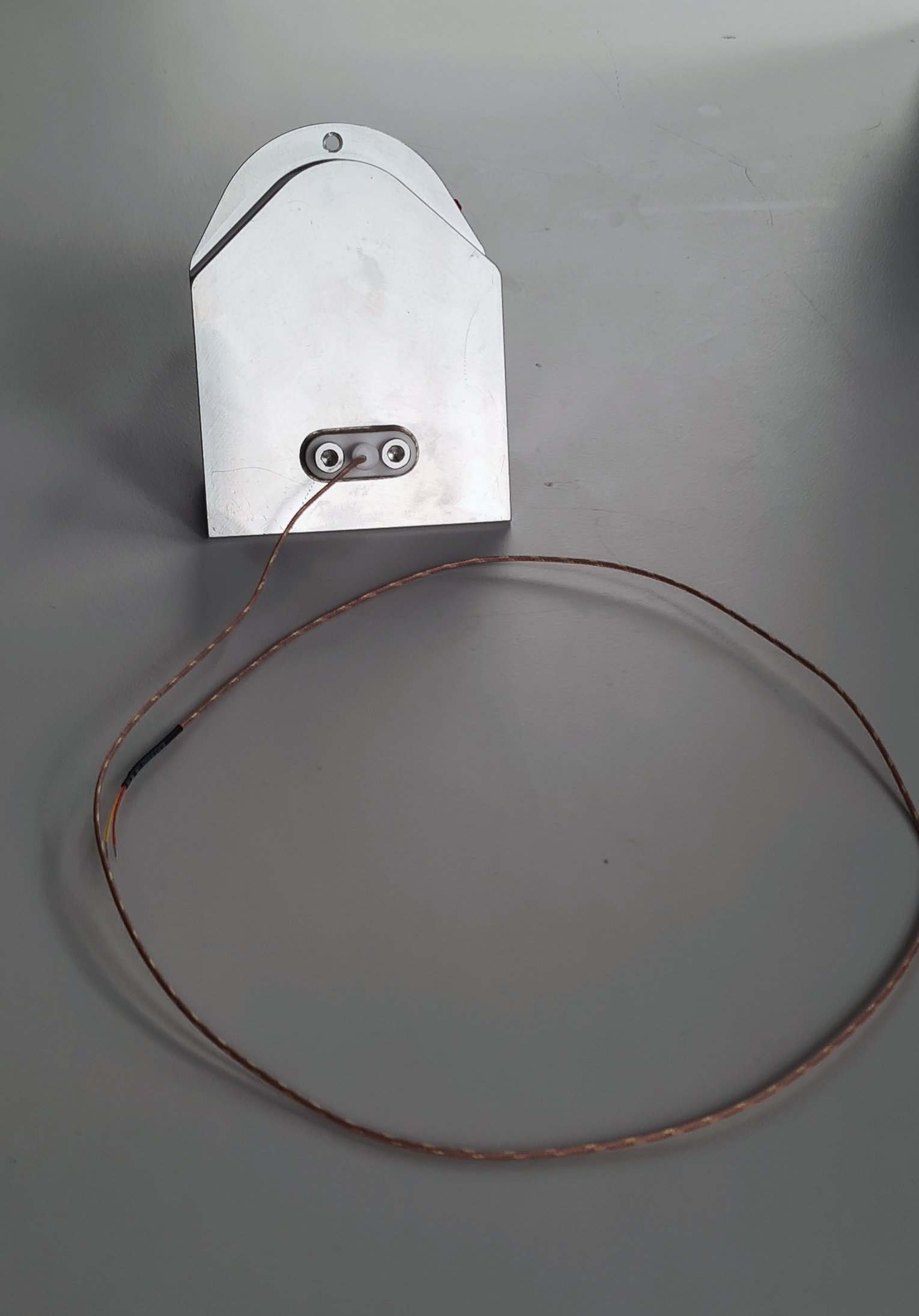
The finished assembled inlet temperature part.
Additional tools needed
2.5-millimeter hexagonal key (L or T-shaped)
Scissors
Slotted screwdriver 2-millimeter
Instructions
before starting - important!
Send an email to support@roestcoffee.com with your order number, production number, and machine name. This information is needed in order to give your machine access to the inlet profiles. Production number and machine name can be found on a sticker at the front of your roaster.

Part 1 - assemble the inlet temperature kit
Unpack the temperature probe. Install the gasket on top of the probe and insert it through the holes in the new housing on the flat side. Push it on until you hear a click. Use the two screws to tighten it into place, but don’t overtighten it as the white piece can break.


part 2 - install the inlet temperature
2. Remove the right-hand side panel.
3. Take off the front décor plate.
4. Only for L100, remove the k-type cable from the PCB. Free the cable from the heater fan.


When you remove the drum temp sensor, leave the connector wide open. The connector on the right is in the correct position, and the connector on the left is in the wrong position.
5. Disconnect the heater fan from the PCB and cut the cable ties holding the cables from the heater fan in place.


6. Disconnect the heating element cables from the wago connectors. Undo the two screws on the heating element lid with a 2.5-millimeter hex key, and lift the heating element away from the housing. Put it aside. NOTE: Before disconnecting, take a photo or make a reference to ensure that the correct cable goes into the correct wago connector when reconnecting. Remove the silicone hose.
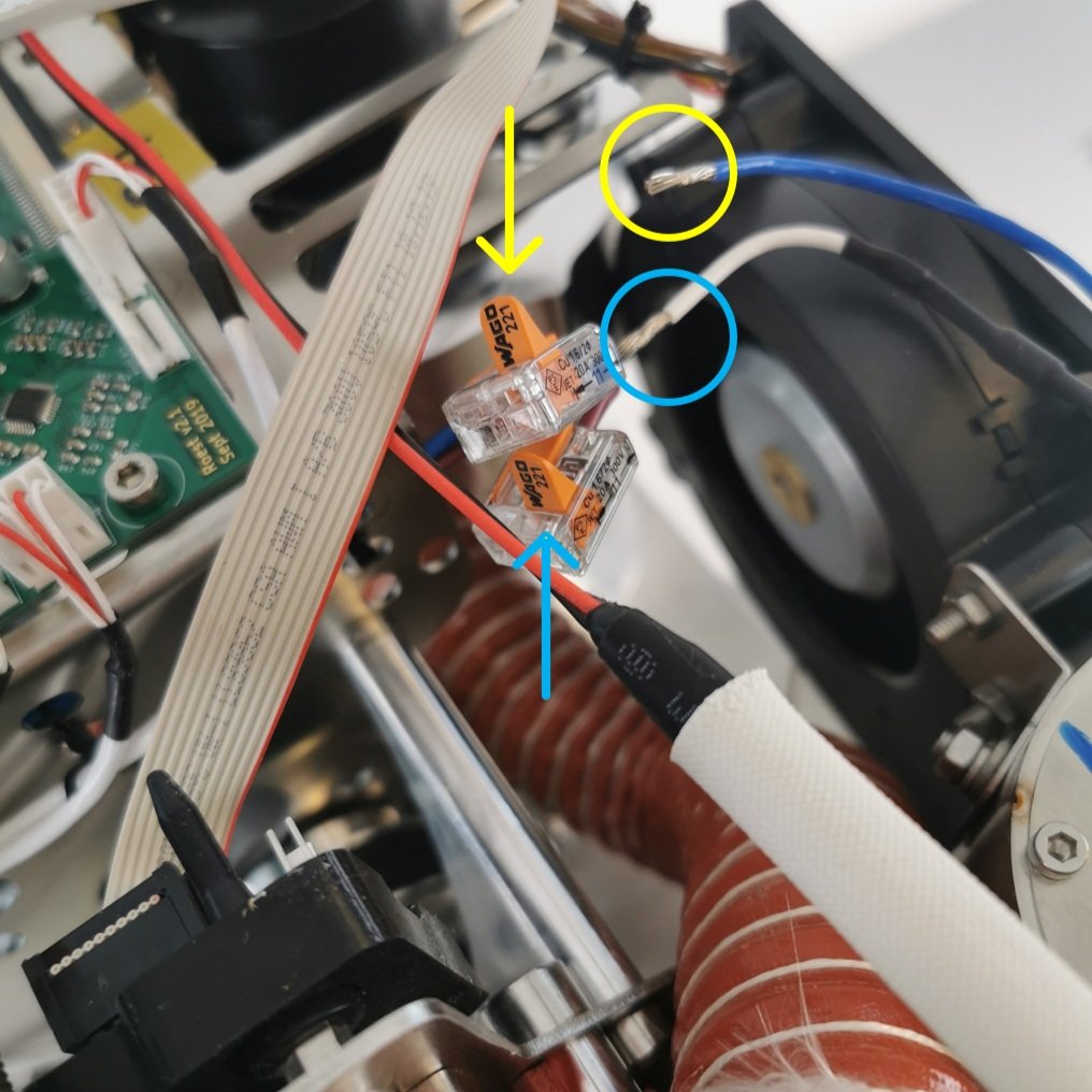
Only open the two flaps that read Wago 221.

7. Remove the six cap head bolts holding the heater fan with the 3-millimeter hexagonal tool.


8. Remove the old heater fan assembly. To do this safely and correctly, follow these steps:

1. Push the heating element housing towards the drum (this will tilt the assembly at approximately 45˚).

2. Pull the heater fan assembly out while maintaining the 45˚ angle. Pull the drum temperature sensor cable out from the holes in the heater fan.
8. Remove the superwool bracket and the superwool.

Superwool and bracket
9. Remove the heating element housing from the heater fan by loosening the following three screws.

The tool you received with your kit should be long enough to reach this screw.

Leave the bolts loose like this, do not remove them yet.
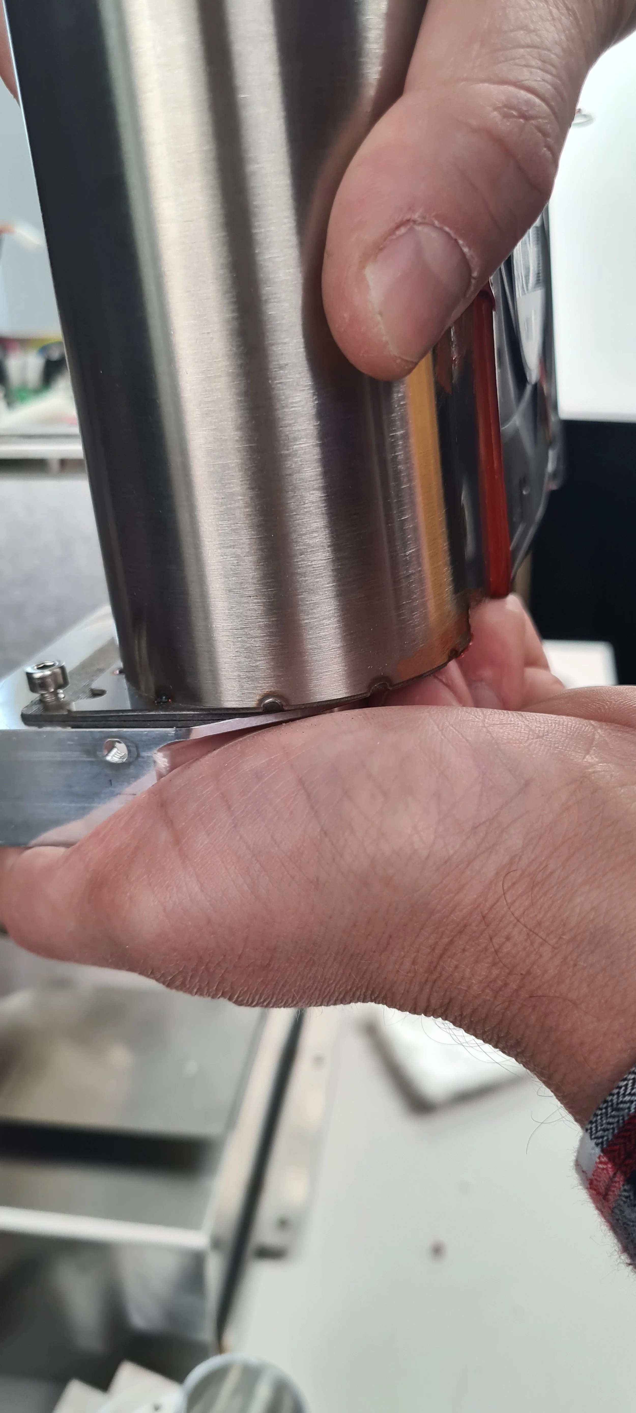
Slide the housing away from the two front bolts.
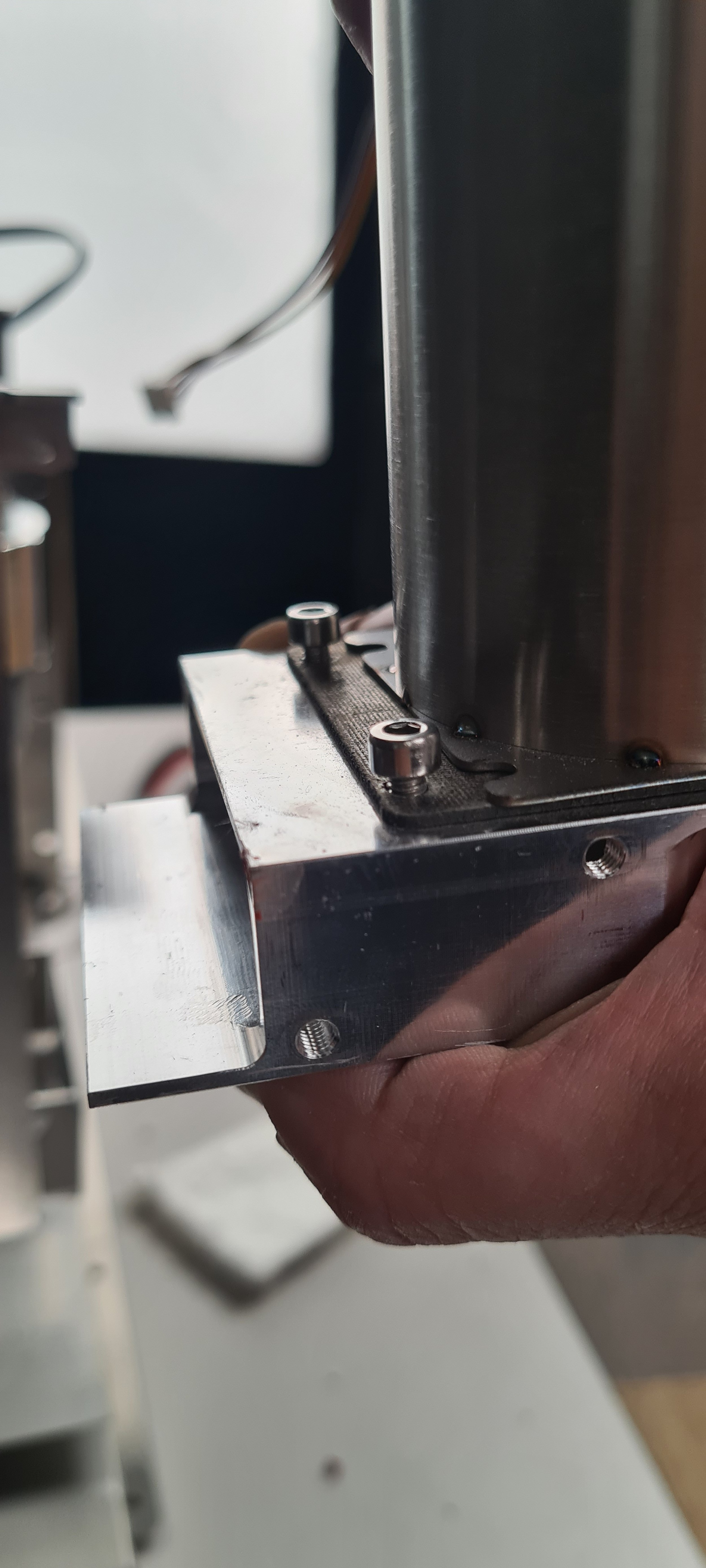
Slide the housing away from the two bolts; now, the housing is free to be removed. Lift the housing upwards to remove it.
10. Remove the old inlet housing and install the new one with the inlet temperature.

Remove the mica tube by pulling it out.

Undo the three bolts and remove them.

Remove the spacer from the old inlet housing.

Install the spacer on the new inlet housing by leaving all three screws loosely done.

Leave space between the bolts and the housing.

Slide the heater fan on the new inlet housing, push it forward until the heater fan covers the spacer, and tighten the three screws. Install the mica tube again.
11. Install the heater fan with the new inlet temperature.

Cut the super wool in half.

Slide the inlet temperature probe through the slit while lifting up the superwool.

Slide the heater fan in place.

Make sure there is no gap.
Loosely install the six head bolts holding the heater fan in place. With the bolts loose, push the heater fan as close as possible to the drum, then tighten the four outermost bolts. Install the super wool and the bracket, tightening the remaining two bolts. Reinstall the heating element.
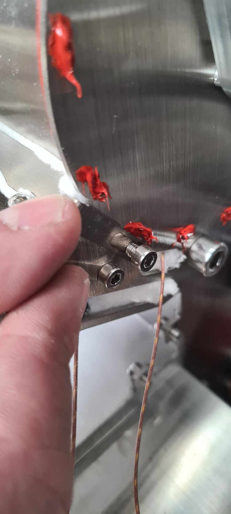
Push the bracket down as much as possible and make sure the screws secure the bracket.

Make sure the orientation of the heating element is correct. The red rubber component should be closer to the PCB.
12. Install and connect the cables.

Find the two k-type sensors and pull them out towards you, so they are easily available; the inlet temperature sensor will be marked with black tape so you can easily recognize it.

Pull the drum and inlet sensors through the two holes in the heater fan.

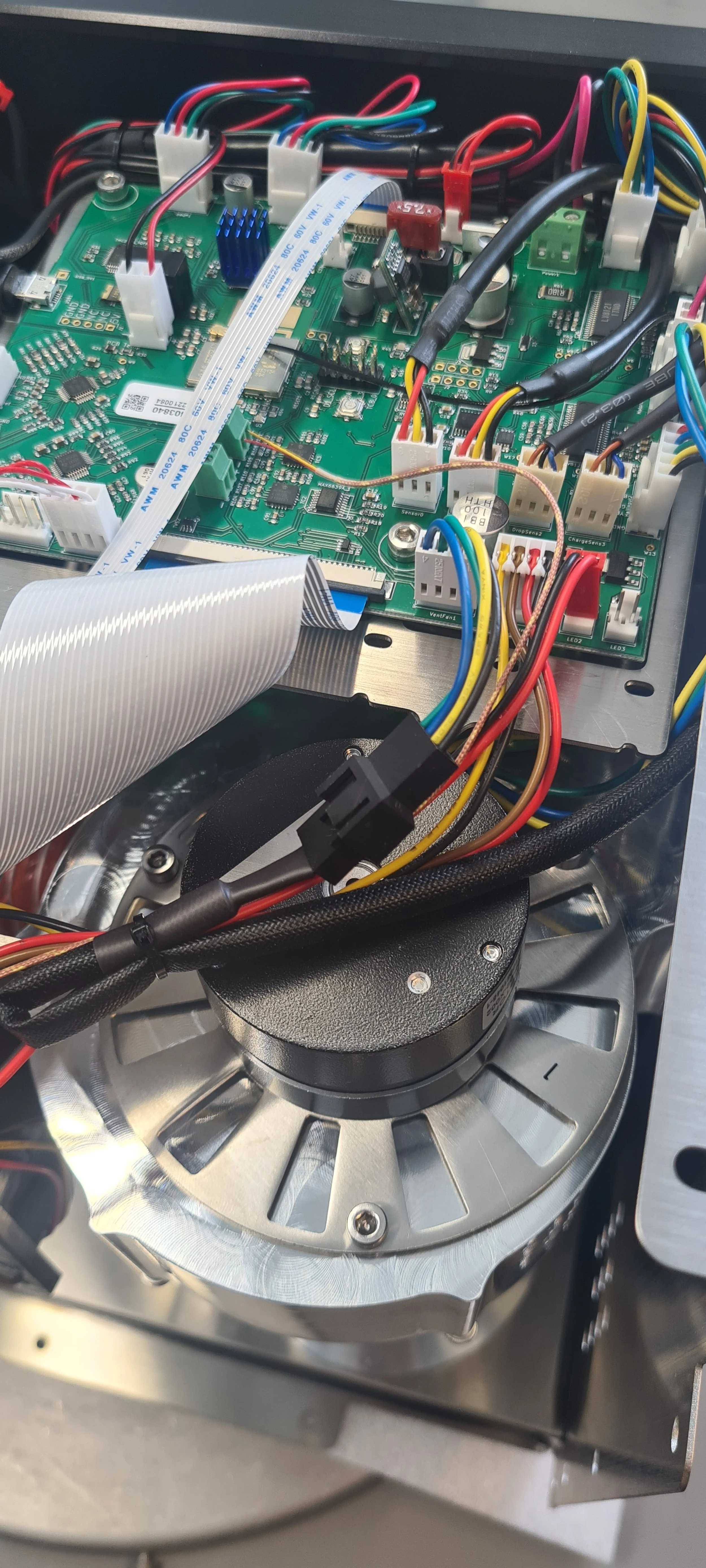
Install the drum and inlet temperature sensors in the screw terminals. Ensure that the drum and inlet are installed into the proper terminals and that the polarity is correct. The right positions are shown in the photo above.
Reconnect the heater fan and the heating element cables (use the reference photo you took at the beginning to ensure they are inserted correctly). Reinstall the orange hose for the exhaust. Use the new cable tie where you cut the cable tie at the beginning of the process.
13. Install the front décor plate. Instructions here.
14. Install the side panels. Find instructions here.
15. Install the top plate following this guide.
You are now ready to use your new inlet temperature sensor!
Video instructions
Having issues?
Cabling
A guide to how the cables within the machine are tied and how you should tie them up if having to undo them when changing a component or doing repairs.
Why do we use cable ties?
We use cable ties on our cables for safety reasons and to keep them neat inside the machine. If you have to change a component, the probability of having to cut some cable ties and redo them is significant. Trying to navigate the cables within the machine can be overwhelming, especially where they go and what they do. This guide aims to help you in case of having to navigate our cables and cable tie system.
Left-hand side - Motor bracket
The three pictures below show how most cables are tied to the motor bracket.

Top view, what you see when removing the top plate.

The left side of the motor bracket is seen when the left-hand side panel is removed.

The right side of the motor bracket is seen when the left-hand side panel is removed.
Left side of the motor bracket:
We have the power cables to the heating element on the left side of the motor bracket. It is crucial that these are tied alone on this side and do not touch any other cables. Below the motor bracket, it is hard to separate them entirely from other cables, but one should try as much as possible.
Right side of the motor bracket:
On the right side, we have the rest of the cables going from the PCB to one of the components at the bottom of the roaster (SSR, power pack, buzzer, etc.). On this side there are a few things to notice:
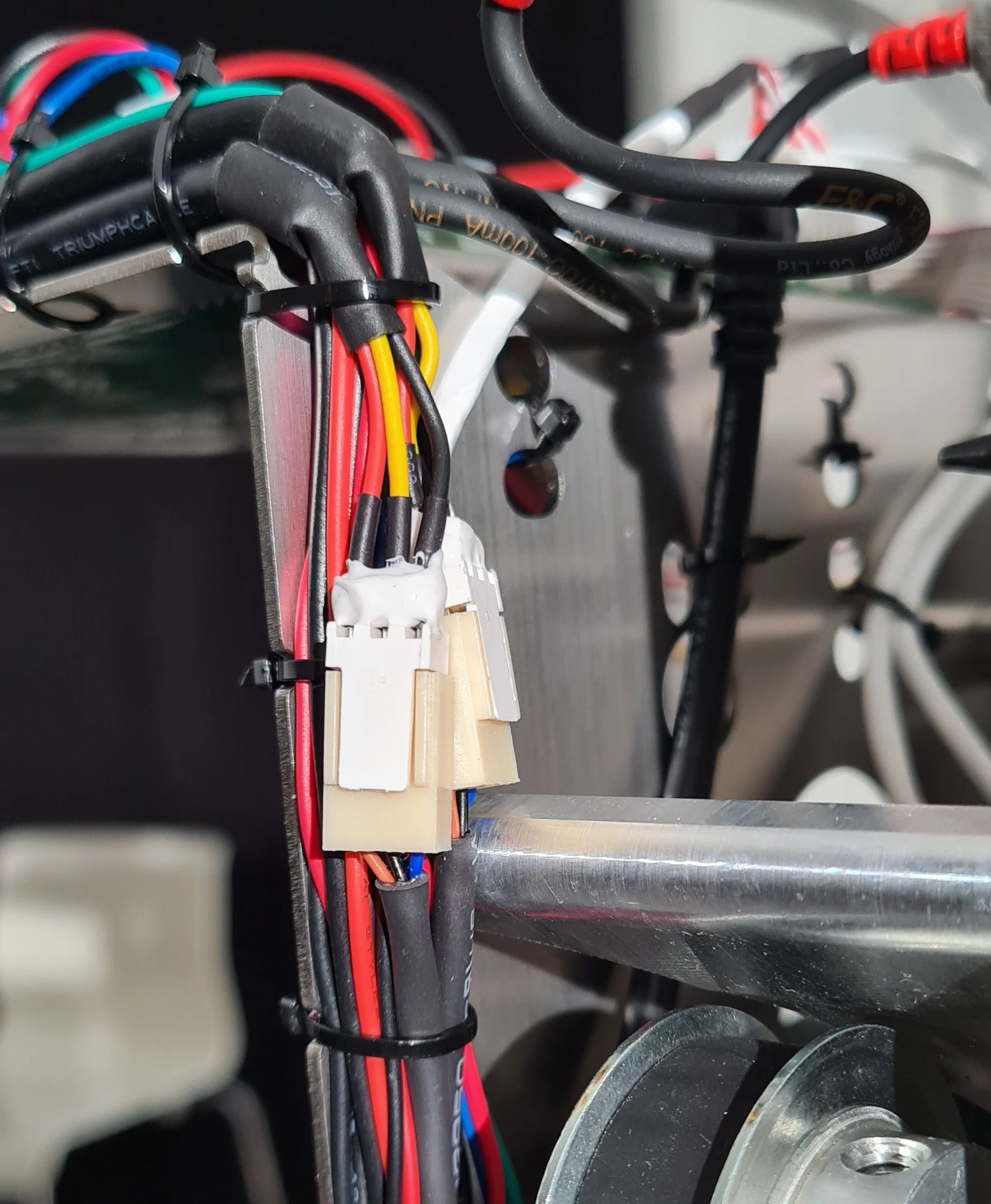
These are the extension cables to the RPM and Cooling tray proximity sensors. It is very crucial that the white connectors or the cables close to them are not crushed by cable ties. They should rather be kept loose from the cable ties in this area, like it’s been done in the photo.

The ET and Exhaust temperature sensors should be tied like in the photo above. Make sure not to let the cables touch the pulley.

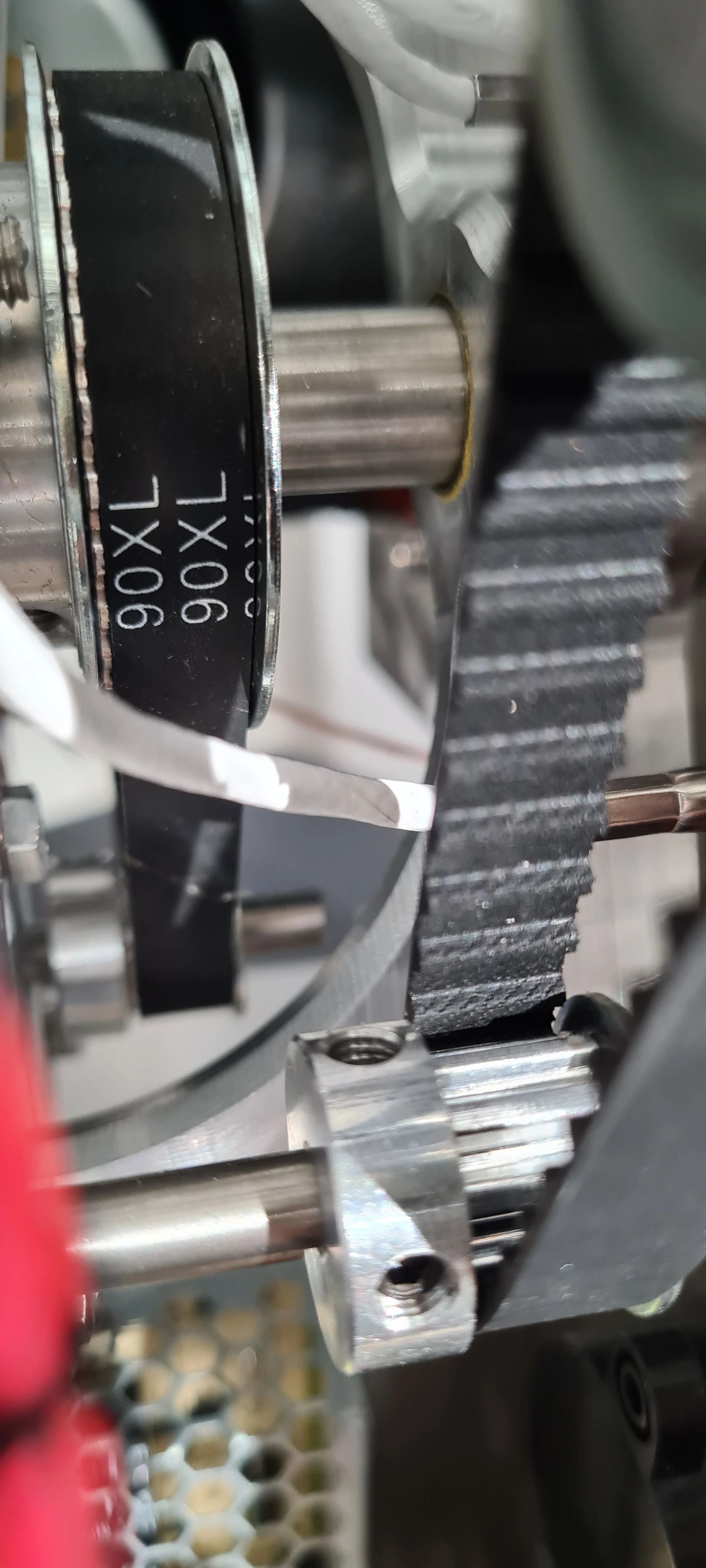

The BT temperature sensor is positioned between the two pulleys, and you should ensure not to let the BT temperature cable touch them. The third photo shows how the BT cable must be positioned around the Y-piece to get it out of the way from the pulleys.
Right-hand side

The heater fan, chassis fan, drum temperature sensor, and LED window cables are tied to the motor bracket on the right-hand side if you look from the top.
Chassis fan

Cables should be kept out of the chassis fan in the back.

Cables can get stuck in the chassis fan; there will be a loud sound from this area if that is the case.
Maintenance
Maintenance of your sample roaster determines how well it performs. To keep up the quality of your roasted coffee, follow the basic cleaning schedule of your ROEST sample roaster.
Here you can find the recommended cleaning schedule for your ROEST machine. Before starting, make sure to follow the safety instructions!
How often you need to clean your machine depends on how often you roast, how many batches you’ve roasted, how dark you roast, and the size of your batches. Oil and fat especially will be difficult to remove with time.
Sections:
Before you start
⚠️DISCLAIMER
Information in this document is believed to be accurate and reliable. However, the manufacturer does not give any representations or warranties, expressed or implied, as to the accuracy or completeness of such information and shall have no liability for the consequences of the use of such information. The manufacturer is not liable or responsible for any problems arising from the attempted repair. The manufacturer reserves the right to make changes to information published in this document, including without limitation specifications and product descriptions, at any time and without notice. The manufacturer's products are not designed, authorized, or warranted to be suitable for use in applications where failure or malfunction can reasonably be expected to result in personal injury, death, or severe property or environmental damage. The manufacturer accepts no liability for inclusion and/or use of its products in such equipment or applications and therefore such inclusion and/or use is for the customer’s own risk.
⚠️SAFETY INSTRUCTIONS
make sure the roaster is turned off
the power cord has to be unplugged
follow the steps as instructed below
FREQUENT CLEANING - every 100 batches or weekly
Depending on your use, after about 100 batches or weekly, your sample roaster needs a quick clean-up. It includes three areas: filter under the bean cooler, chaff drawer, and fan gitter. Before starting, follow the safety instructions!
SAFETY INSTRUCTIONS
Switch off and unplug your roaster before starting.
WHEN
After 100 roasting sessions.
TIME
5-10 minutes
TOOLS
Brush, fiber cloth
steps
FILTER UNDER THE BEAN COOLER
Remove the bean cooling tray and empty the filter. You can also vacuum the area under the bean cooler.
CHAFF DRAWER
Switch off the roaster and unplug it. Open the chaff drawer, remove the airtight foam, empty it (it should be emptied every 20-25 batches), and wipe it with a paper cloth or brush. Read more here.
FAN GITTER
Make sure the roaster is switched off and unplugged. Removing the fan gitter and using compressed air to blow dust away is best. You can also use a dusting cloth and wipe the dust off. If you don’t remove the fan gitter, be careful not to push too much dust into the machine, as it can cause issues with overheating.
recommended: Impellers
It’s wise to pay attention to your impellers as well. After a while, they will be covered with oil and fat from the coffee, and the more regular cleaning you do, the easier you will do a deep clean in the future. For routine cleaning, you don’t have to remove them, but wiping them off as much as possible with a cloth, a brush, or compressed air is wise.
recommended: ventilation exit from the top
The area behind the charge handle can get filled with beans; if not removed, they will melt and become very difficult to remove. First, remove the top plate and then remove the charge handle. Remove any beans that may be stuck there.
Watch the video below with detailed steps of the regular maintenance process.
Recommended steps to add into the frequent cleaning routine:
DEEP CLEANING - AFTER 1000-5000 BATCHES OR MONTHLY
After about 1000-5000 batches, your ventilation should be deep cleaned if you haven’t already. The best practice is to do this regularly, so oil and fat don’t get a chance to build up, making it harder to clean the impellers properly. The process includes two areas: ventilation exit in the back and from the top of the roaster. Follow the instructions to clean your ROEST sample roaster properly.
SAFETY INSTRUCTIONS
Let your ROEST cool down properly. Switch off and unplug the roaster before starting.
WHEN
After 1000-5000 roasting sessions or monthly.
TIME
1hr +
TOOLS
2-millimeter hexagonal key, brush, microfibre cloth, vacuum cleaner or pressurised air, degreasing chemical such as espresso machine detergent or PBW cleaner.
steps
VENTILATION EXIT IN THE BACK OF THE ROASTER
Before starting make sure your roaster is switched off and unplugged.
To clean the ventilation exit in the back of the roaster, remove the ventilation hose. Follow this guide on how to remove the impellers and soak them in hot water and fat remover or espresso detergent.
VENTILATION EXIT FROM THE TOP
Before starting make sure your roaster is switched off and unplugged.
Start with removing the top plate. Carefully place it on the side. Remove the charge handle. Clean the ventilation exit using a brush. If beans or dirt has melted into the metal, the part can be removed and soaked in hot water and fat removal/espresso detergent.
Roaster overview
The following images show an overview of the front and back of your ROEST.
Sections:
Front overview
1. HOPPER for adding beans to the roaster.
2. BEAN CHARGE HANDLE for dropping the beans into the drum.
3. ROTARY ENCODER KNOB for adjusting settings.
4. BEAN DROP HANDLE for preheating the drum or manually releasing the beans.
5. BEAN TRIER for checking beans during the roasting process.
6. TOUCHSCREEN for full manual mode (displaying parameters and adjusting variables).


Machine parameters
If you would like to adjust your machine settings, you can access them via Machine Setup on the touchscreen.
1. Bean cooling duration: Duration of increased speed after drop.
2. Bean cooling %: Percentage speed after drop.
3. Bean cooling idle %: Percentage speed while idling.
4. Temperature reading: Celsius or Fahrenheit.
5. Bean cooler light and Window light: Can be turned ON or OFF.
6. Cool. tray warn (BETA): Coming soon.

IMPORTANT. The bean cooling fan is always ON, but can be set to increase in speed when the coffee is dropped.

If you don’t want the bean cooling fan to increase speed after dropping, set the timer to 0 seconds or the fan speed to the same rate as the idling speed.
All about the Service Menu

What is the SERVICE MENU
The service menu is a secret/hidden menu for troubleshooting purposes guided by the Support team. Here you can find a guide on how to find this menu and all recommended settings available to you.
Important: Do not change anything (except listed here) in the service menu unless recommended by our support team.
How to enter Service Menu
Service menu is hidden in the right bottom corner of the main menu:

1. Enter the main menu.

2. Tap on the bottom right corner of the screen, then toggle the knob.

3. “SERVICE” will pop up.
Recommended PID Settings
These are the recommended values for PID settings. First - read above: How to enter Service Menu.

1. Go to SERVICE MENU

2. Press on Adjust PID

3. These are the recommended values for PID settings.
(Important note: Add to AirT, Add to BT, and Add to InletT are for calibration and should not be changed without dialog with ROEST. These values are unique for each machine).
Recommended Ventilation Settings
These are the recommended values for VENTILATION settings. First - read above: How to enter Service Menu.

1. Go to SERVICE MENU

2. Press on SETTINGS

3. These are the recommended values for VENTILATION settings.
If your Roest is situated at 1200m above sea level or higher, you should increase the heater fan setting (3600rpm or more), to boost airflow and to extend the lifespan of your heating elements.
How to change: Proximity sensor - RPM
How to replace your RPM (Motor) Proximity sensor.
Sections:
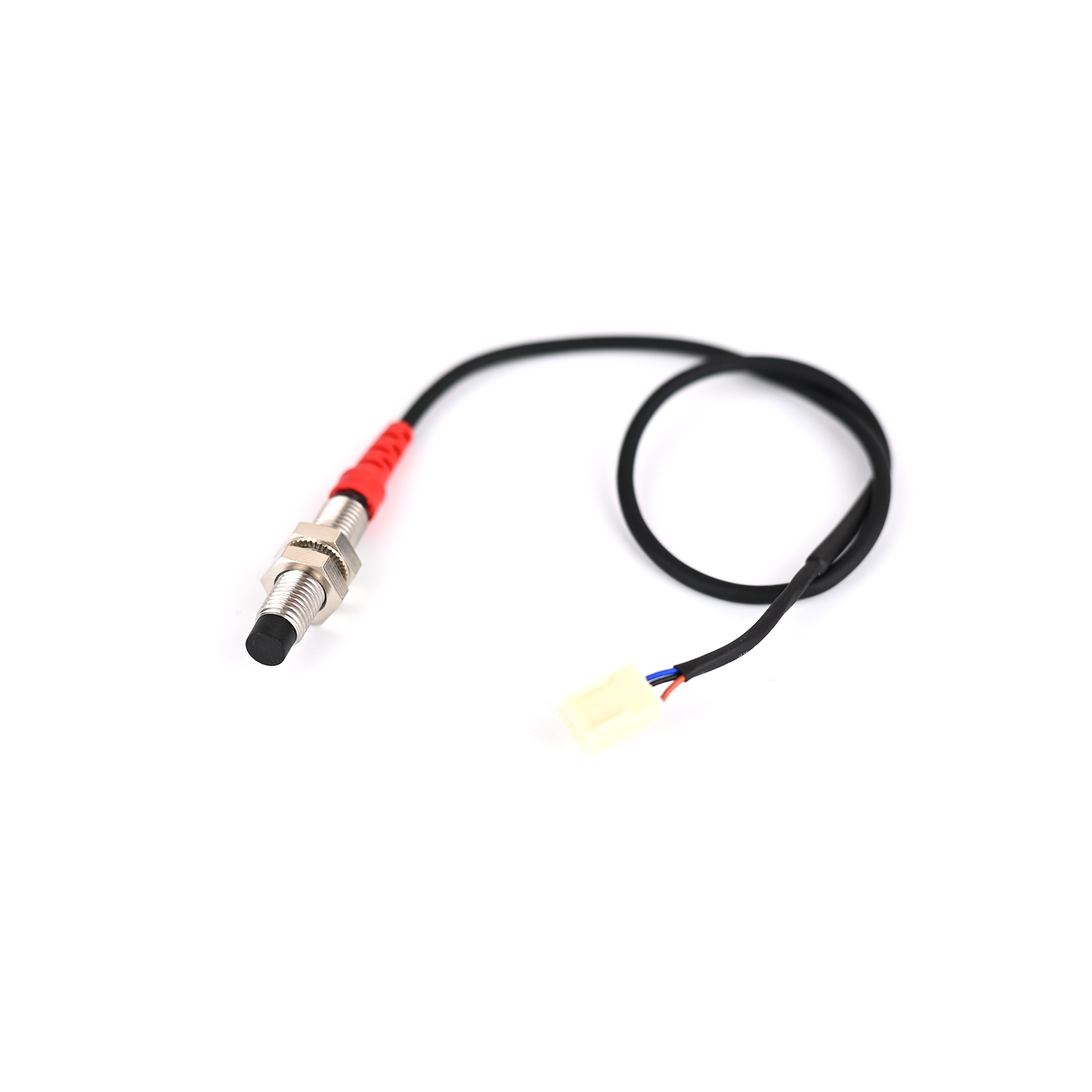
When to replace your RPM Proximity sensor
If you have issues with the motor, it could be due to a faulty proximity sensor. Be sure to check that your motor gear ratio settings are correct, and before buying a new sensor, go through our troubleshooting guide for the RPM proximity sensor.
Where to buy a Proximity Sensor
Your spare universal proximity sensor was sent along with your ROEST. You must place an order if you no longer have a spare one. The nonflushed type is recommended for the motor RPM, but both work.
Before you start
⚠️DISCLAIMER
Information in this document is believed to be accurate and reliable. However, the manufacturer does not give any representations or warranties, expressed or implied, as to the accuracy or completeness of such information and shall have no liability for the consequences of the use of such information. The manufacturer is not liable or responsible for any problems arising from the attempted repair. The manufacturer reserves the right to make changes to information published in this document, including without limitation specifications and product descriptions, at any time and without notice. The manufacturer's products are not designed, authorized, or warranted to be suitable for use in applications where failure or malfunction can reasonably be expected to result in personal injury, death, or severe property or environmental damage. The manufacturer accepts no liability for inclusion and/or use of its products in such equipment or applications and therefore such inclusion and/or use is for the customer’s own risk.
⚠️SAFETY INSTRUCTIONS
make sure the roaster is turned off
the power cord has to be unplugged
follow the steps as instructed below
Tools

12-millimeter spanner.
Instructions
Before starting - remove the top plate and lefthand side panels.
Place your roaster, so you have a good view of the sensor.

View of the proximity sensor from the left-hand side. Take a photo or note how the cables are tied along the metal bracket. The most important thing is to separate the two left cables (burgundy and blue) from the right side cables.

Close-up of the proximity sensor.
Use the 12-millimeter spanner on the nuts holding the sensor in place, and unscrew the sensor from the bracket. The sensor cable is tied along the metal bracket (called the motor bracket), and all of these ties need to be removed. Remove the old sensor from the PCB, and connect the new one. Feed the cable down the metal bracket the same way as the old one, and cable tie all the cables the same way it was before. When fitting the RPM proximity sensor, ensure the distance between the RPM plate and sensor is not too great; it should be as small as possible without them touching. The sensor should flash red when the machine is powered on.
You can carefully test the roaster without the panels on to see if you need to adjust the distance some more; make sure not to heat it up.
When finished, reassemble the side panels and top plate.
PCB overview
Here you can see a complete overview of the PCB.

YELLOW:
Exhaust fan 5 pin connector
Extra LED light/24v output
LED light window
Heater fan
Chassis fan (large computer fan at the back)
Touch screen
Exhaust temperature pt-100
Extra temperature pt-100
Air temperature pt-100
Bean temperature pt-100
RED:
Drop handle sensor
Charge handle sensor
RPM proximity sensor (monitors paddles)
Bean cooler warning sensor
First crack detection
Inlet K-type temperature sensor
Drum K-type temperature sensor
Wi-Fi antenna
Buzzer
BLUE:
Exhaust fan 3 pin connector
Power heating element (Solid state relay)
Bean cooler fan 5 pin connector
Bean cooler fan 3 pin connector
LED light bean cooler
Encoder
Chamber motor
Drop door motor
USB
Motor gear ratio explained
There are two pulleys and a timing belt connecting the motor and the paddles.

Depending on your model, the ratio between the two pulleys differs. On nearly all roasters up to p16, we had a 1:1 gear ratio, meaning the two pulleys were of equal size.
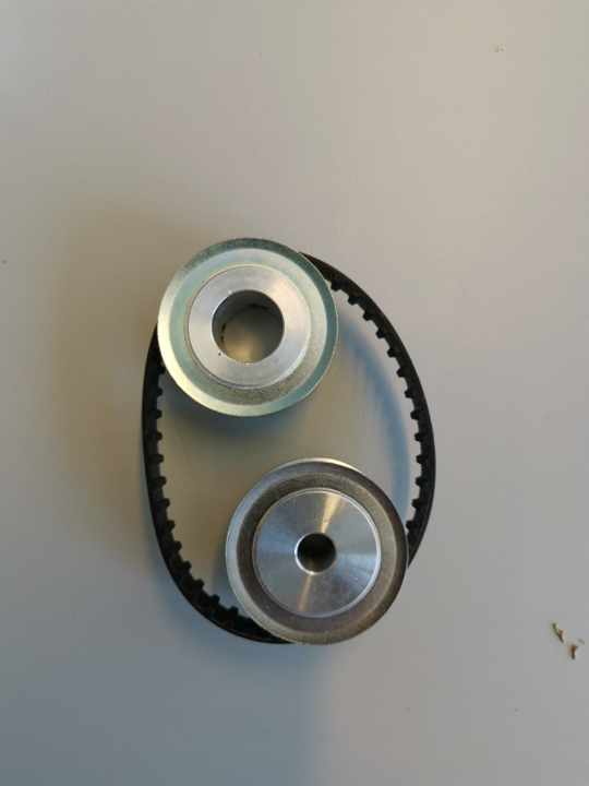

On some p16, we started using a 2:1 gear ratio to get double the torque.

Then we changed to 3:1 for more torque. 3:1 is now standard.

To improve performance with 3:1 gearing, we removed component r25 on the PCB. By removing r25, the setting in the menu must be 12:1. Gear ratio is 3:1, but the firmware needs 12:1.
Check your gear ratio settings in the service menu if you are experiencing issues with the motor, either by a warning message on the touchscreen, odd movements, or sounds from the drum. What gear ratio your machine should have depends on the model (what pulley ratio it has) and if the PCB has the r25 chip or not:
1:1 gearing + r25 on PCB = 1:1 gear ratio in service menu
2:1 gearing + r25 on PCB = 2:1 gear ratio in service menu
3:1 gearing + r25 on PCB = 3:1 gear ratio in service menu
1:1 gearing – (minus) r25 on PCB = 4:1 gear ratio in service menu
2:1 gearing - (minus) r25 on PCB = 8:1 gear ratio in service menu
3:1 gearing - (minus) r25 on PCB = 12:1 gear ratio in service menu
How to change: Impellers
How to change and clean the impellers on your ROEST.

Where to buy new impellers?
New impellers are only necessary if you have the older version and wish to upgrade or if they are broken. If your impellers are not spinning, the motor needs to be changed, not the impellers. Contact our Support Team in this case or go to our e-shop to buy new ones (one for each side). If you wish to buy new impellers, go here:
Before you start
⚠️DISCLAIMER
Information in this document is believed to be accurate and reliable. However, the manufacturer does not give any representations or warranties, expressed or implied, as to the accuracy or completeness of such information and shall have no liability for the consequences of the use of such information. The manufacturer is not liable or responsible for any problems arising from the attempted repair. The manufacturer reserves the right to make changes to information published in this document, including without limitation specifications and product descriptions, at any time and without notice. The manufacturer's products are not designed, authorized, or warranted to be suitable for use in applications where failure or malfunction can reasonably be expected to result in personal injury, death, or severe property or environmental damage. The manufacturer accepts no liability for inclusion and/or use of its products in such equipment or applications and therefore such inclusion and/or use is for the customer’s own risk.
⚠️SAFETY INSTRUCTIONS
make sure the roaster is turned off
the power cord has to be unplugged
follow the steps as instructed below
Tools

2.5-millimeters, 3-millimeters, and 4-millimeters hexagonal key.

Cutters.

Philips screwdriver

Flat ended screwdriver
You will also need a 1-millimeter spacer (can be anything, a piece of paper or similar).
Parts
The set consists of a left impeller and a right impeller. They are specific to their side. Our team should mark the impellers before shipping them so you can know their differences.
Instructions
Before starting - remove the top plate and both side panels.
Removing the chaff separator

1. Orientate the roaster with the exhaust duct facing the operator.
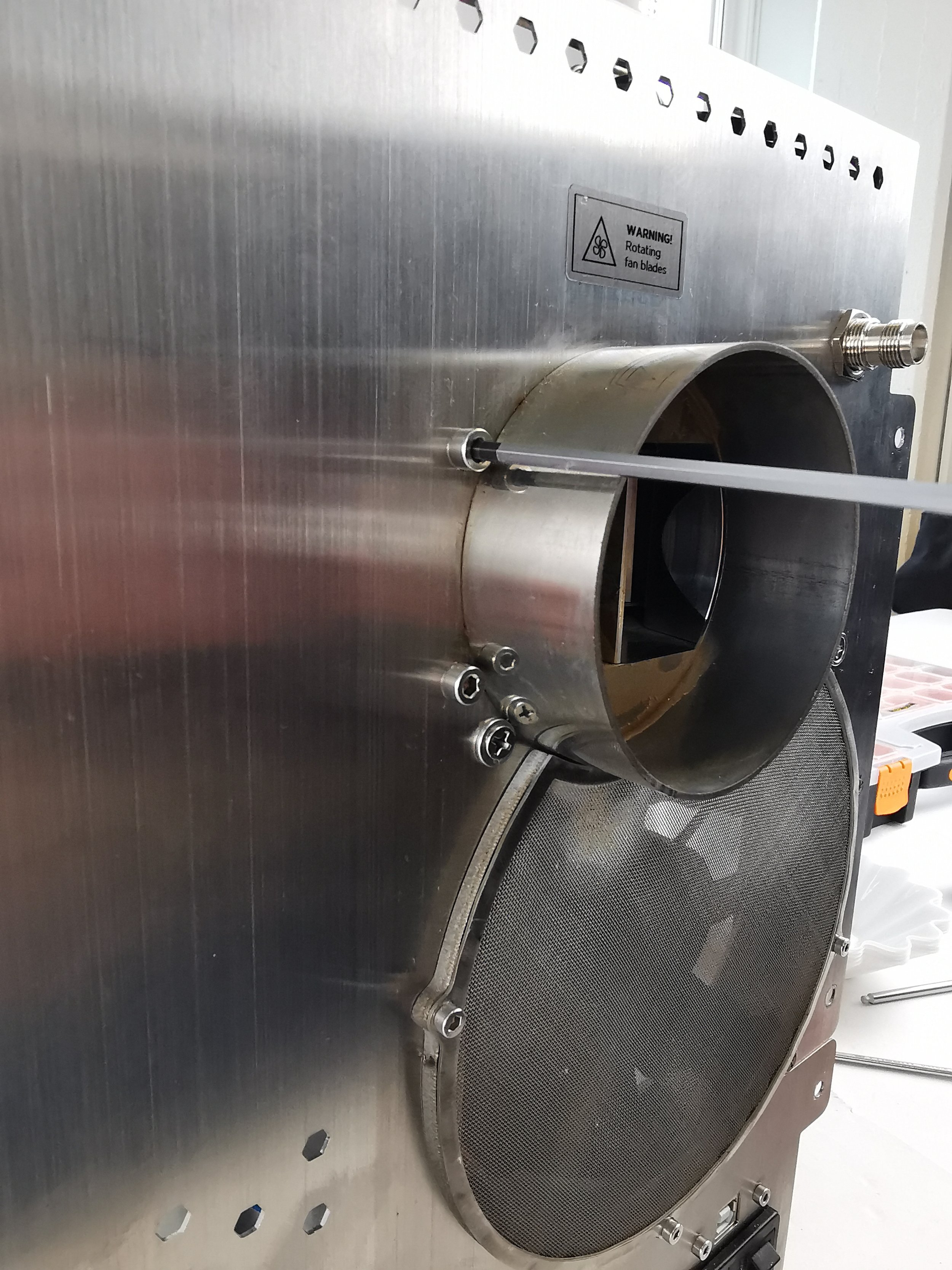
2. Remove four off M4 x 6 cap head screws around the exhaust duct holding the chaff separator.

3. Disconnect the tube from the chaff separator and exhaust duct from the bean stopper.

4. Disconnect the tube from the chaff separator and exhaust duct from the bean stopper.

5. Disconnect fan connectors from PCB marked 1, 3, and 4 in blue and 1 in yellow.

6. Disconnect the tube from the chaff separator and exhaust duct from the bean stopper.

7. Remove one off M3 x 6 cap head screw from the mesh to separate the back panel from the chassis.

9. The chaff separator is now free and can be removed from the inside of the roaster.

8. Unscrew three off M5 x 8 screws from the chaff drawer. NB: ensure that the split washers on the M5 x 8 screws are kept on the screws. The screw on the innermost side doesn’t need to be fully removed, only loosened enough to allow the chaff separator to slide out.
Removing the impellers

1. Place the chaff separator with the brushless motors facing the desk.

2. Unscrew ten off M4 x 6 cap head screws.
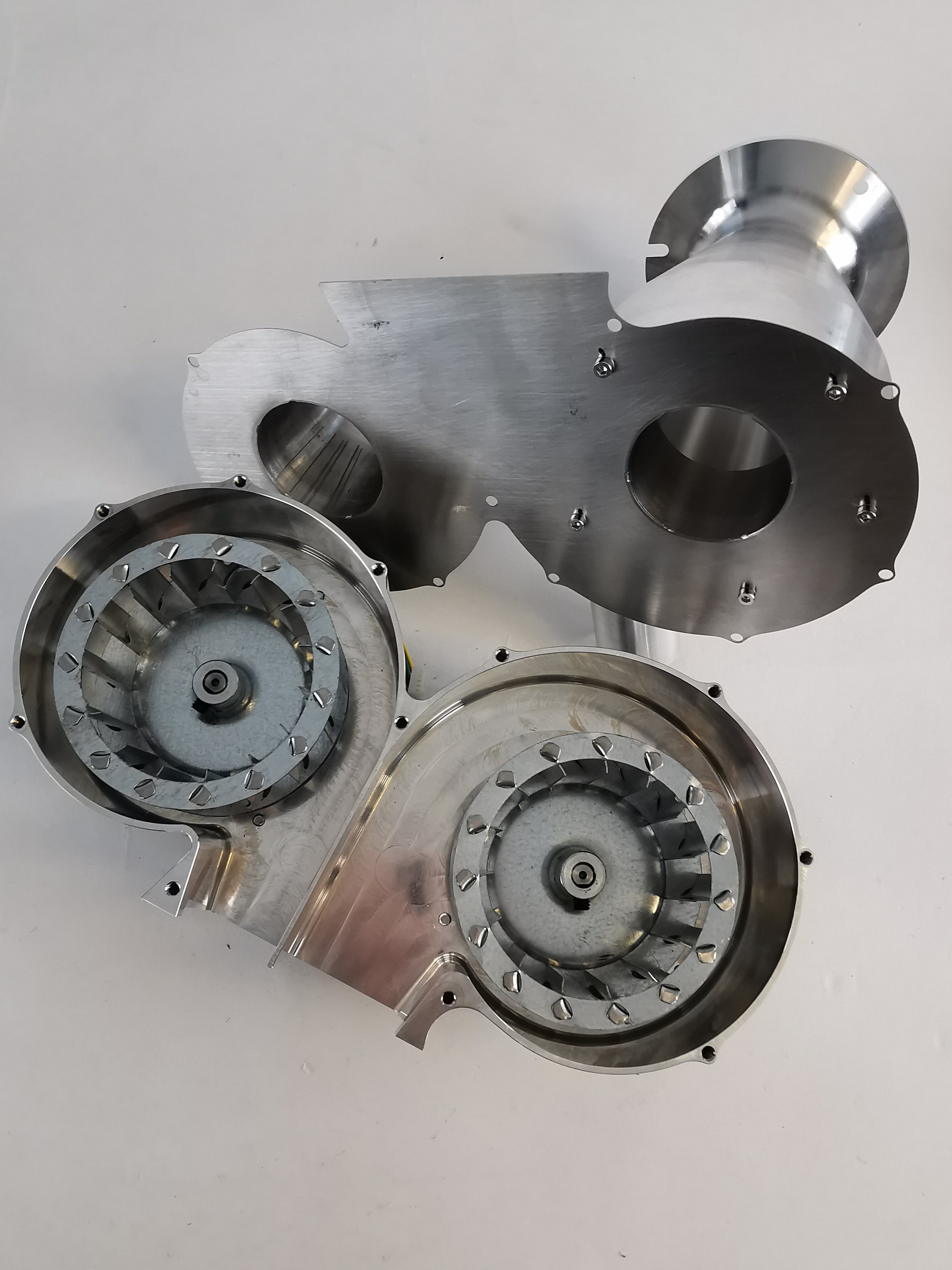
3. Separate the air intake housing from the cyclone separator to access the impellers.
NB: a flat screwdriver may need to be used to separate due to the build-up of chaff and oil.

4. Take an image/refer to the orientation and location of the left and right impellers before removing them. NB: the impellers are speci fic. They must be installed on the correct side for the chaff separator to work correctly.

5. Use a 4-millimeter hexagonal key to loosen the impeller on both the left- and right-hand sides.
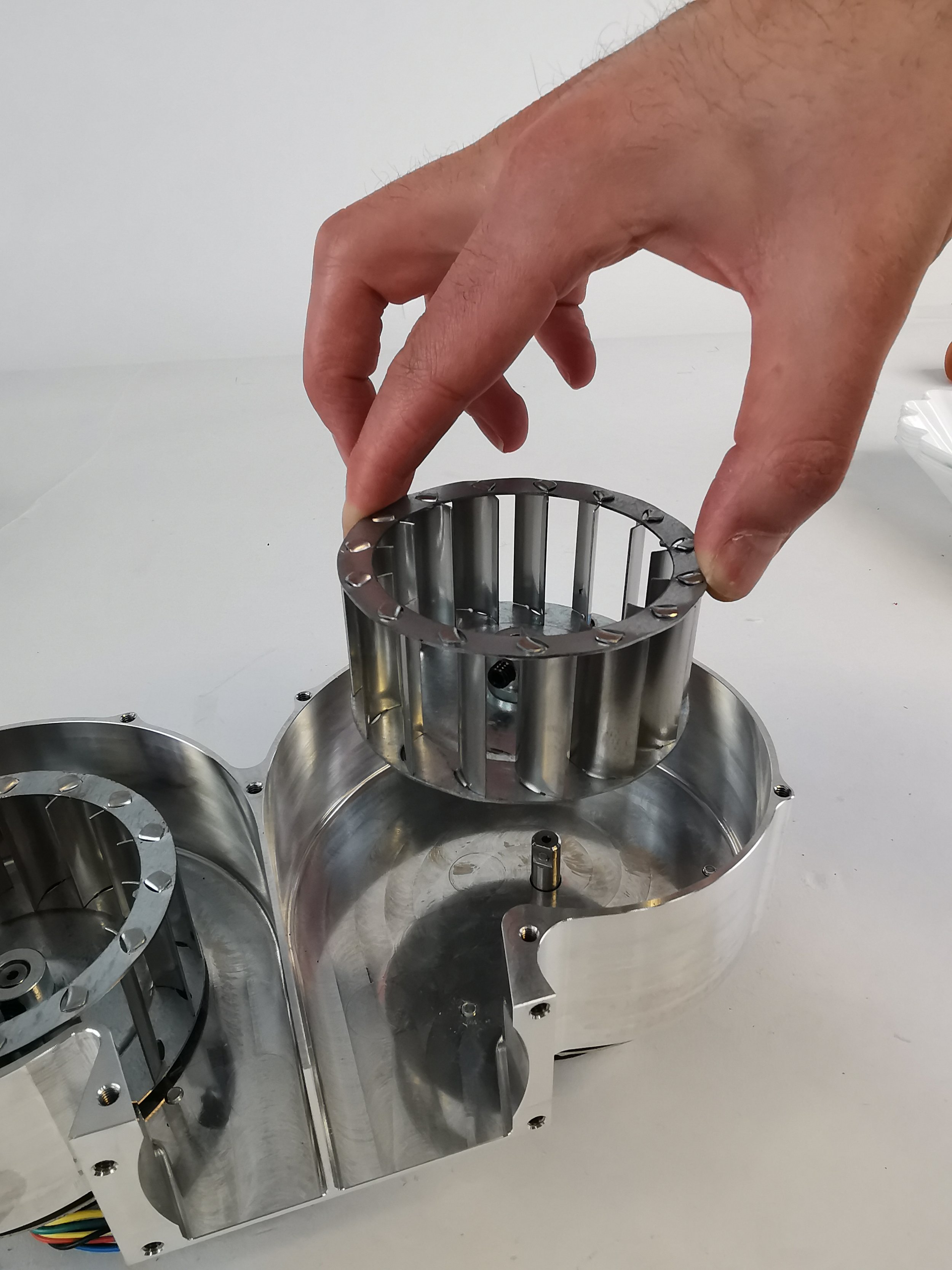
6. Lift the impellers from the motor shaft. Repeat for each side.

7. The impellers are now free for you to clean, or you can install new ones.
Optional: cleaning the impellers
At this point, your impellers can be cleaned if you wish to. We use a fat cleaner and let the impellers soak in this for a while. Afterward, we wash it off with soapy water. You can use a brush if you need to, but be careful not to remove the balancing clip from the impeller if it has one.
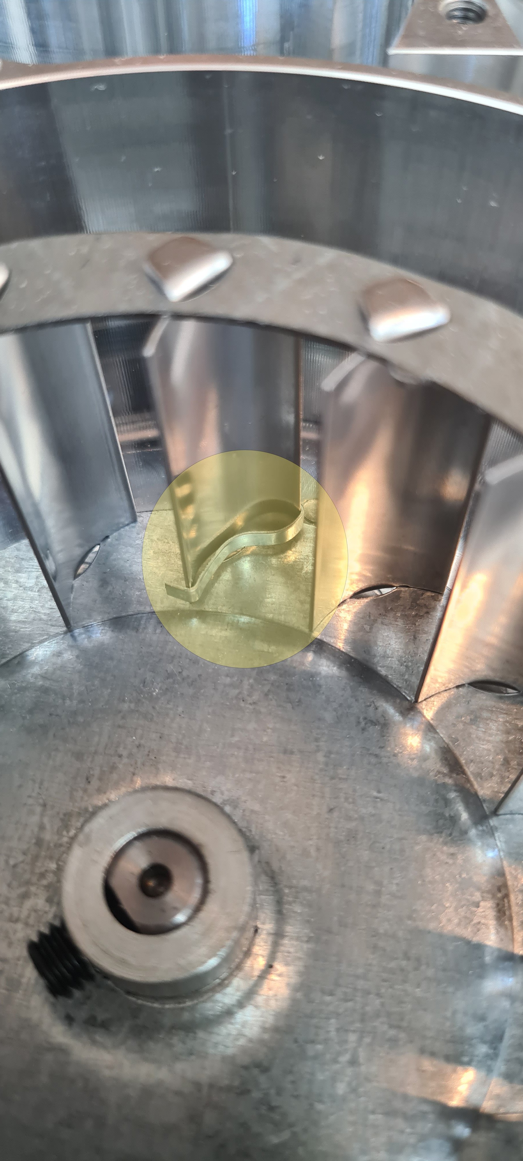
The balancing clip.
Installing the impellers
When installing the impellers, place a 1-millimeter-thick spacer on the face of the impeller housing. The spacer can be a piece of paper, cardboard, or something similar. It is just there to create a gap between the impellers and the impeller housing.

1. Install the impeller on the shaft on top of the spacer and tighten the grub with a 4-millimeter hexagonal key. Remove spacer. Repeat for the other side.

2. Place the cyclone separator on top of the air intake housing.

3. Screw all M4 x 6 cap head screws to secure both components together.

4. Locate the re-assembled chaff separator into the chaff drawer and align the exhaust with the rear.

5. Screw 3 M5 x 8 screws into the chaff drawer and tighten.

6. Screw 4 M4 x 6 cap head screws through the back panel into the chaff separator and tighten.

7. Screw 1 of M3 x 6 cap head screw through the mesh to attach the back panel from the chassis.
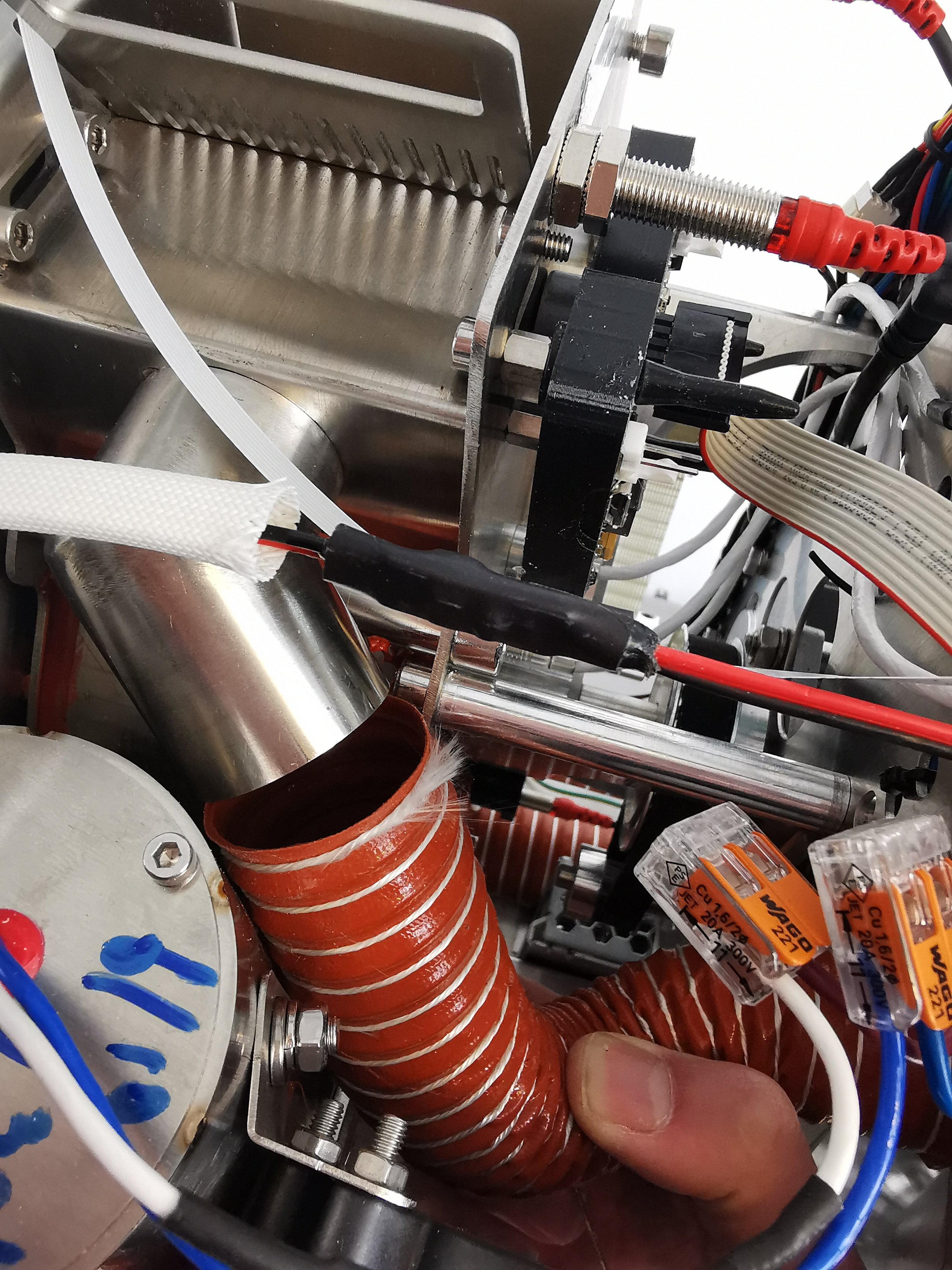
8. Reconnect the exhaust and bean cooler pipes.

9. Reconnect the exhaust and bean cooler pipes.
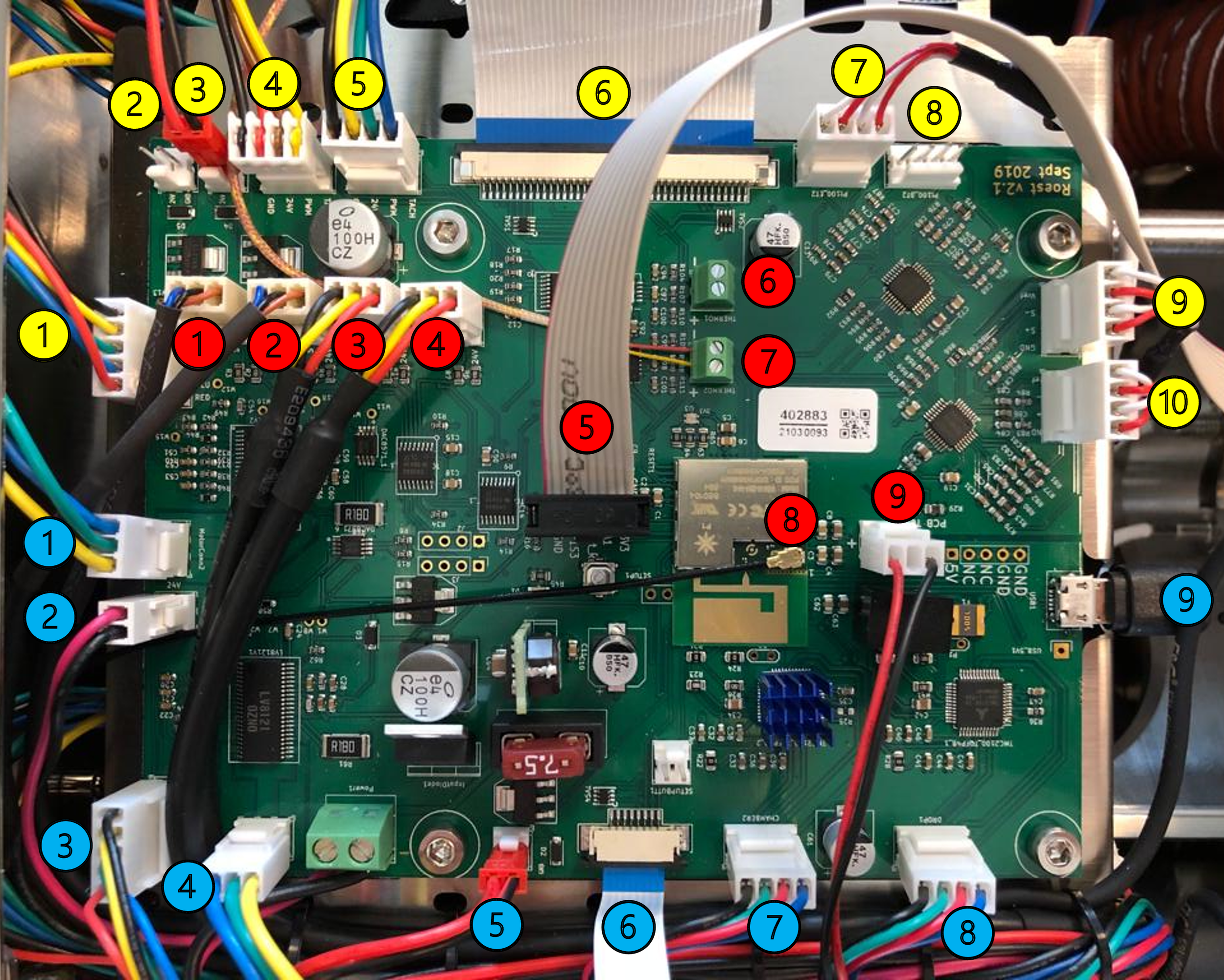
10. Connect fan connectors from PCB, marked 1, 3, and 4 in blue and 1 in yellow.
Reattach the side panels and top plate.
How to change: Chassis fan
How to change the chassis fan on your ROEST.
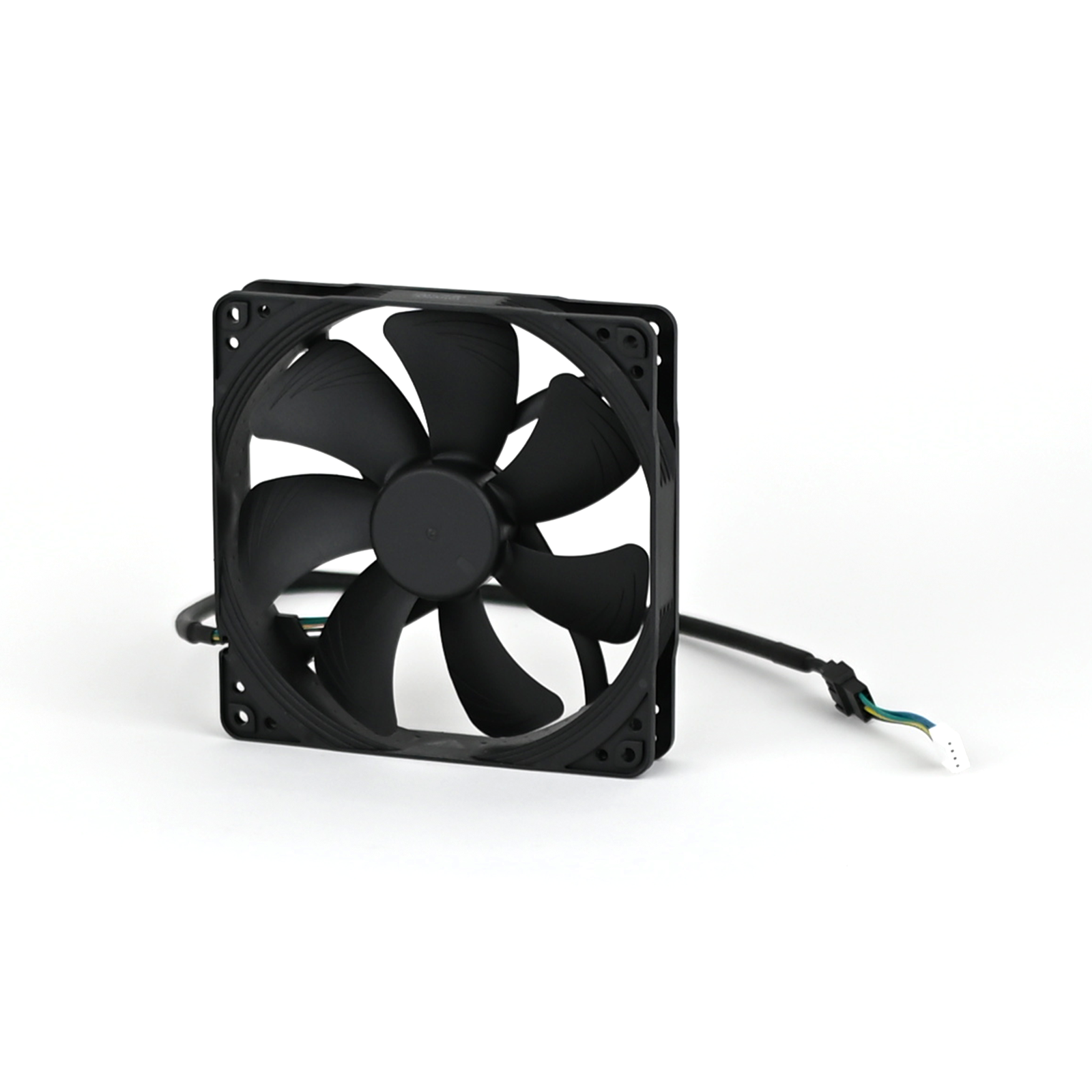
Where to buy a chassis fan?
If you are sure your chassis fan is broken (you have talked to our Support Team) visit our e-shop to purchase a new one!
Before you start
⚠️DISCLAIMER
Information in this document is believed to be accurate and reliable. However, the manufacturer does not give any representations or warranties, expressed or implied, as to the accuracy or completeness of such information and shall have no liability for the consequences of the use of such information. The manufacturer is not liable or responsible for any problems arising from the attempted repair. The manufacturer reserves the right to make changes to information published in this document, including without limitation specifications and product descriptions, at any time and without notice. The manufacturer's products are not designed, authorized, or warranted to be suitable for use in applications where failure or malfunction can reasonably be expected to result in personal injury, death, or severe property or environmental damage. The manufacturer accepts no liability for inclusion and/or use of its products in such equipment or applications and therefore such inclusion and/or use is for the customer’s own risk.
⚠️SAFETY INSTRUCTIONS
make sure the roaster is turned off
the power cord has to be unplugged
follow the steps as instructed below
Tools

Cutters

Philips screwdriver
Parts

Chassis fan

Cable ties
Instructions
2. Remove the left side panel.
3. Disconnect the connector from PCB and the extension cable from the fan cable. NOTE: the extension cable can be reused for the replacement fan.
4. Cut any cable ties fastening the cable to the roaster.
5. Pull the cable through, so it is loose and hanging from the roaster.
6. Take a photo/reference of the orientation of the ventilation fan before removal. NOTE: fan is meant to draw air into the roaster to keep components cool.

The correct orientation of the fan is shown in the image on the left, seen from the inside of the roaster.
7. Orientate the roaster, so the back is facing you.
8. Using the Phillips screwdriver bit, remove the four fourscrews holding the fan in place.

NOTE: Screws have split washers on them, please take care not to lose them!
9. Remove the old ventilation fan.

10. Locate the new fan in the correct orientation.

11. Fasten all four bolts until tight.

Align holes on the fan with holes on the back of the roaster before installing bolts
12. Feed cable over the top of the chaff separator.
13. Attach extension cable to fan connector.
14. Attach the connector to PCB.
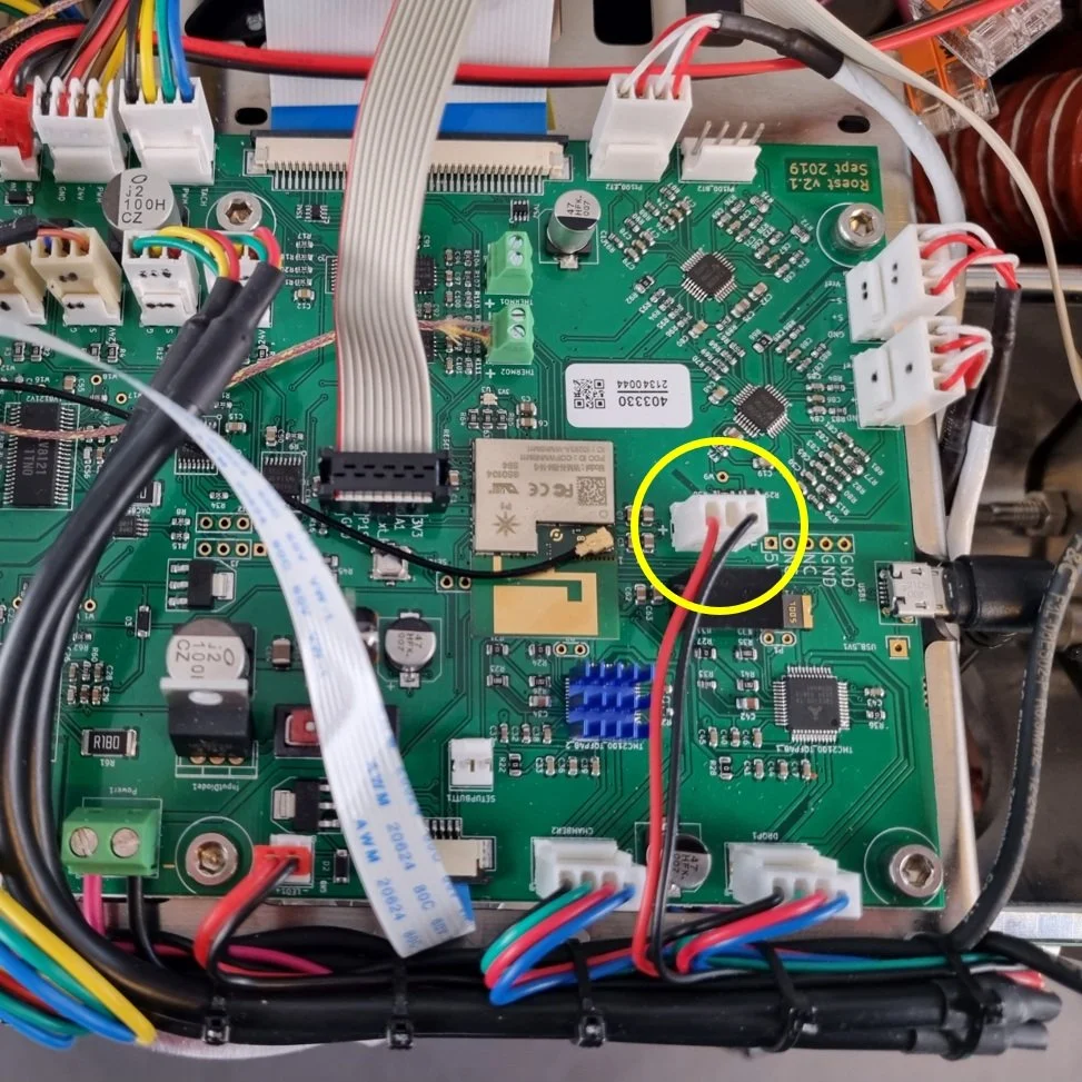
NOTE: PCB reads “VentFan1”
15. Fasten any loose cables to the roaster.
16. Install the left side panel.
18. Plug the roaster in, turn it on and test the chassis fan. If it doesn’t work, contact the ROEST support team.
How to change: Buzzer
This is the guide on how to change the buzzer on your ROEST.

Where to buy buzzer?
If you are sure your buzzer is broken (you have talked to our Support Team) visit our e-shop to purchase a new one!
Before you start
⚠️DISCLAIMER
Information in this document is believed to be accurate and reliable. However, the manufacturer does not give any representations or warranties, expressed or implied, as to the accuracy or completeness of such information and shall have no liability for the consequences of the use of such information. The manufacturer is not liable or responsible for any problems arising from the attempted repair. The manufacturer reserves the right to make changes to information published in this document, including without limitation specifications and product descriptions, at any time and without notice. The manufacturer's products are not designed, authorized, or warranted to be suitable for use in applications where failure or malfunction can reasonably be expected to result in personal injury, death, or severe property or environmental damage. The manufacturer accepts no liability for inclusion and/or use of its products in such equipment or applications and therefore such inclusion and/or use is for the customer’s own risk.
⚠️SAFETY INSTRUCTIONS
make sure the roaster is turned off
the power cord has to be unplugged
follow the steps as instructed below
Tools

Flat ended screwdriver

Cutters
Parts

Buzzer

Cable ties

M5 x 6 cap head screw
Silicone
Instructions
2. Remove the left side panel.
3. Take a photo of the cable location on the PCB and how cables are fastened to the motor bracket ((LED1) on PCB) to know where to relocate and fasten the new component.
Buzzer connector on PCB

Cables fastened to motor bracket ((LED1) on PCB)
4. Remove the buzzer connector from PCB.

5. Using the small flat-ended screwdriver, pry the faulty buzzer away from the back plate.


6. Cut the cable ties to release the buzzer. NOTE: Take care not to cut through any cables.


Only cut the amount of cable ties required to release cable.
7. Apply four silicone dots around the buzzer, approximately 10-millimeter in size.

8. Install the buzzer.

Locate the M5 x 6 screw through the front of the back plate

Locate buzzer hole into screw and press onto the back plate.
NOTE: Ensure that the orientation of the cable is the same as in the image.
9. Plug the buzzer cable back into the PCB.

10. Cable tie the buzzer back into position.

11. Use cutters to trim the excess ends from cable ties.

12. Leave silicone to dry for approx. 30 minutes before reassembling.
13. Remove the M5 x 6 cap head screw after the silicone has been left to dry for 30 minutes.

14. Install the left side panel.
16. Plug the roaster in, turn it on and test the buzzer. If it doesn’t work, contact the ROEST support team.
How to change: Power supply
This is the guide on how to change the power supply on your ROEST.

Where to buy power supply?
If you are sure your power supply is broken (you have talked to our Support Team) visit our e-shop to purchase a new one!
Before you start
⚠️DISCLAIMER
Information in this document is believed to be accurate and reliable. However, the manufacturer does not give any representations or warranties, expressed or implied, as to the accuracy or completeness of such information and shall have no liability for the consequences of the use of such information. The manufacturer is not liable or responsible for any problems arising from the attempted repair. The manufacturer reserves the right to make changes to information published in this document, including without limitation specifications and product descriptions, at any time and without notice. The manufacturer's products are not designed, authorized, or warranted to be suitable for use in applications where failure or malfunction can reasonably be expected to result in personal injury, death, or severe property or environmental damage. The manufacturer accepts no liability for inclusion and/or use of its products in such equipment or applications and therefore such inclusion and/or use is for the customer’s own risk.
⚠️SAFETY INSTRUCTIONS
make sure the roaster is turned off
the power cord has to be unplugged
follow the steps as instructed below
Tools

2.5-millimeter hexagonal key

Padded mat

Philips screwdriver
Parts


Using the Philips screwdriver loosen the hose clip

Pull off the exhaust tube

Pull off the exhaust tube
4. Take a reference picture of the location of the cables prior to removing them.

5. Remove the 5 horse-shoe cables from the power supply.

Loosen the screws with the Philips screwdriver

Cables removed
6. Place the padded mat on the desk and lay the roaster down on its side, ensuring that the mat protects the right-side panel (which remains installed).

Padded mat should be underneath
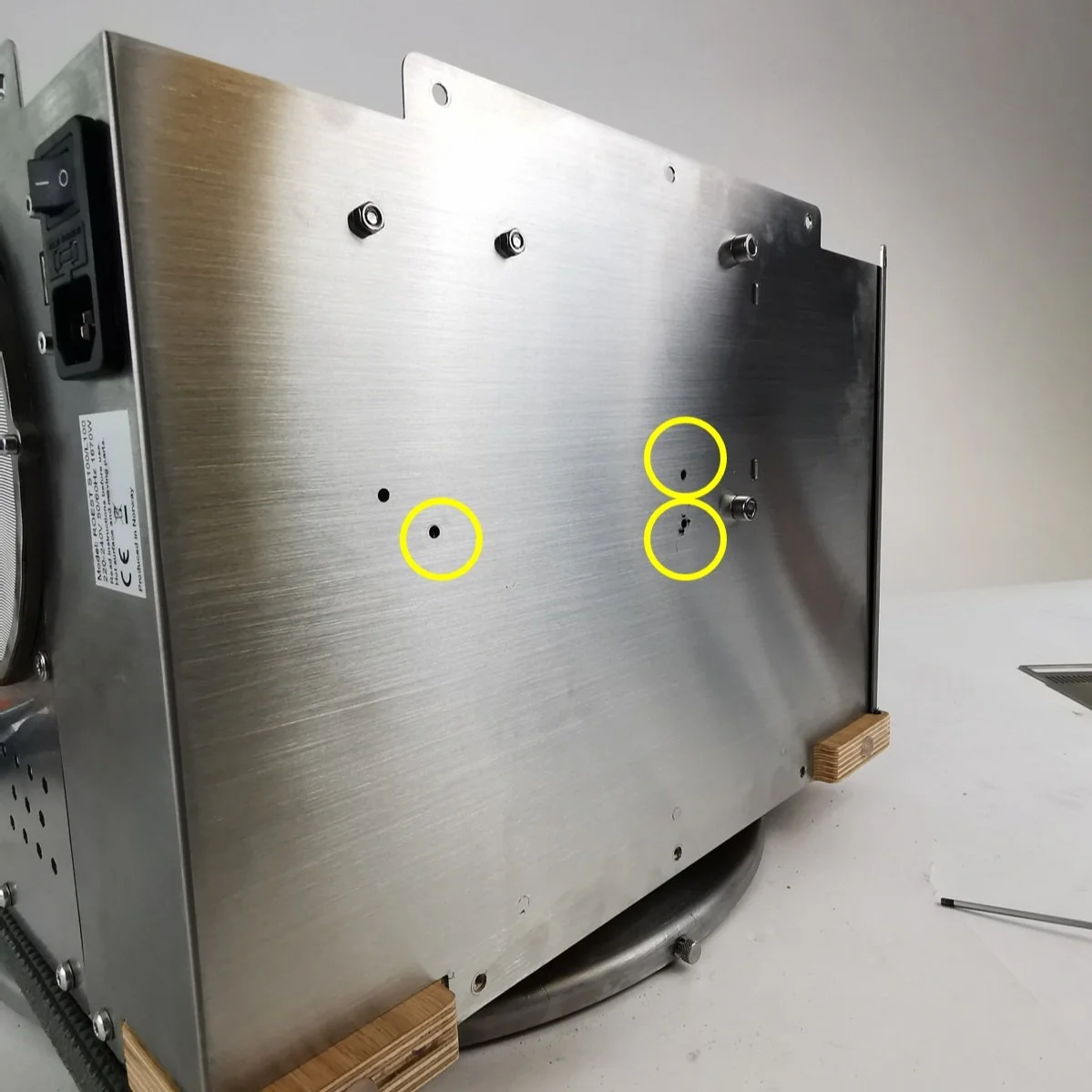
7. Using a 2.5-millimeter hexagonal key, remove the three cap head bolts on the roaster’s base.

8. Remove the power supply from the roaster.

9. Insert the new power supply and align the holes to screw the three bolts on the base.
10. Position the roaster back up.
11. Reattach the five cables into the power pack using the image taken in step 4.

12. Reattach the exhaust tube.
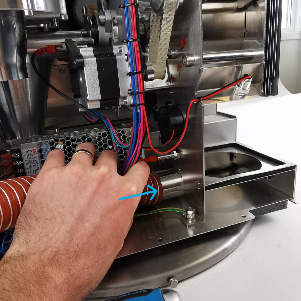


Ensure that you fasten the hose clip around the chaff separator
13. Install the left side panel.
15. Plug the roaster in, turn it on and test it. If it doesn’t work, contact the ROEST support team.
How to remove and install side panels

Before you start
⚠️DISCLAIMER
Information in this document is believed to be accurate and reliable. However, the manufacturer does not give any representations or warranties, expressed or implied, as to the accuracy or completeness of such information and shall have no liability for the consequences of the use of such information. The manufacturer is not liable or responsible for any problems arising from the attempted repair. The manufacturer reserves the right to make changes to information published in this document, including without limitation specifications and product descriptions, at any time and without notice. The manufacturer's products are not designed, authorized, or warranted to be suitable for use in applications where failure or malfunction can reasonably be expected to result in personal injury, death, or severe property or environmental damage. The manufacturer accepts no liability for inclusion and/or use of its products in such equipment or applications and therefore such inclusion and/or use is for the customer’s own risk.
⚠️SAFETY INSTRUCTIONS
make sure the roaster is turned off
the power cord has to be unplugged
follow the steps as instructed below
Tools

2-millimeter and 4-millimeter hexagonal tool
T20 Torx screwdriver or 3-millimeter hexagonal tool.

Padded mat
How to remove side panels
1. Place the roaster on a padded mat to provide a solid base for the machine to stand on once the side panel is removed so it is easier to work with.
3. Remove the trier and the cooling tray to work easier.
4. With the 2-millimeter hex tool, remove the countersunk bolt from the front décor plate (bottom left at the front).

For left side panel removal
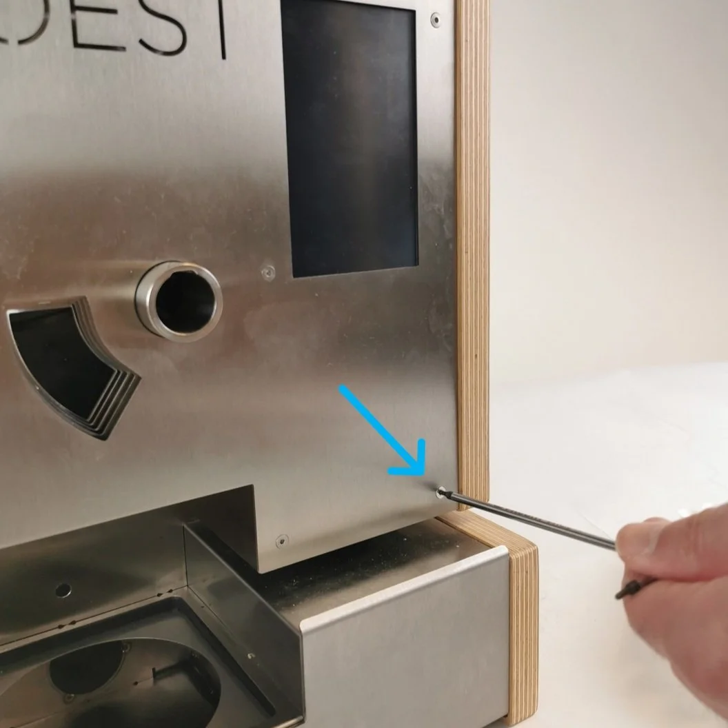
For right side panel removal
5. Remove the screws at the back. Depending on the machine model, you must use a TX20 (wood) or a 3-millimeters hex tool (black). Some older models have three screws instead of four.

For left side panel removal

For right side panel removal
6. Remove the three screws under the roaster corresponding to the panel you want to take off. You can gently lay the roaster on its side or push the machine to the edge of the table so that the line of screws is visible.

Lay the roaster gently on its side.

Or push the machine to the edge of the table so that the line of screws is visible.
7. When you are taking off the side panel, loosen the cap head bolt (on the inside of the machine) holding the panel in place using the 4-millimeters hex tool.


8. Gently take the side panel off and place it on a protective surface to keep it safe.

How to install side panels
1. Start installing the side panel from the front and below. Fit the sleeve bearing in the wooden panel into the small metal projection on the side.

Metal projection

Sleeve bearing
2. Fit the brackets into the metal plates.

The side bracket of the panel goes inside the front plate

The back bracket of the panel goes below the backplate
3. When installing the left side panel, install the cap head bolts with the 4-millimeters hex tool once it is in place. Tighten it while pushing the roaster together.

Unfired bolt

You can use your body as a counterweight
4. Take the 2-millimeter hex tool and tighten the countersunk bolt on the front. Do not overtighten it.

For left side panel installation

For right side panel installation
5. Install the back screws and the bottom screws. Do not fully tighten them until the last one is in its place.

Push the machine to the edge of the table when installing the bottom screws
6. Once the last bolt is in, push the roaster together (move the side panels inwards) and tighten the screws (no need to apply a lot of torque). Make sure that no cables are being squeezed.
Video instructions
This video shows how to remove and replace the black side panels, but it can also be used for wooden side panels. The only difference is that the type of screws is different.
How to change: BT temperature sensor

Where to buy temperature sensors?
If you are sure that a temperature sensor in your roaster is broken (you have talked to our Support Team) visit our e-shop to purchase a new one!
Before you start
⚠️DISCLAIMER
Information in this document is believed to be accurate and reliable. However, the manufacturer does not give any representations or warranties, expressed or implied, as to the accuracy or completeness of such information and shall have no liability for the consequences of the use of such information. The manufacturer is not liable or responsible for any problems arising from the attempted repair. The manufacturer reserves the right to make changes to information published in this document, including without limitation specifications and product descriptions, at any time and without notice. The manufacturer's products are not designed, authorized, or warranted to be suitable for use in applications where failure or malfunction can reasonably be expected to result in personal injury, death, or severe property or environmental damage. The manufacturer accepts no liability for inclusion and/or use of its products in such equipment or applications and therefore such inclusion and/or use is for the customer’s own risk.
⚠️SAFETY INSTRUCTIONS
make sure the roaster is turned off
the power cord has to be unplugged
follow the steps as instructed below
Tools

Cutters

10-millimeter wrench
Parts

BT Sensor
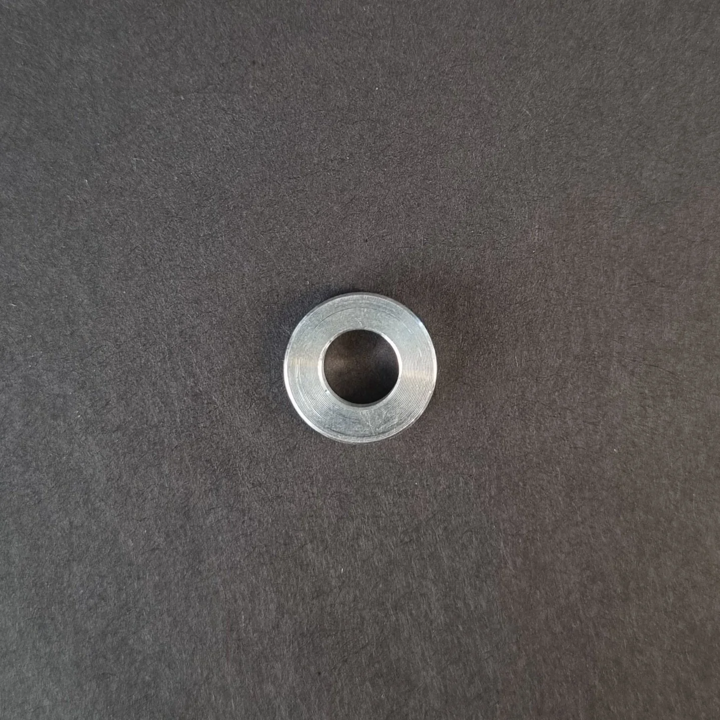
Aluminum Spacer. You will find this on the old sensor.

Cable Ties
Instructions
Follow this numbered guide below step by step.
3. Take a photo/make a reference of cable locations on the PCB so you can reinstall the cables in the correct position.

4. Remove the BT cable from the PCB.

1. Unplug the BT sensor

2. Unplug the USB1 cable

3. Let the BT sensor come out and plug in the USB cable
5. Cut cable ties holding the BT sensor to the motor bracket.

6. Loosen the BT sensor with a 10-millimeter wrench and remove it from the back plate.

7. Take off the aluminum spacer from the BT sensor.

8. Place the aluminum spacer on the new BT Sensor.
9. Locate the BT sensor in its threaded hole by hand, ensuring that the aluminum spacer stays on the BT sensor and continue until finger tight.

NOTE: when rotating the BT sensor by hand, ensure that there is little resistance so as not to damage the thread.
10. Tighten with a 10-millimeter wrench. Do not overtighten, as this can strip the thread and scrap the back plate.
11. Plug BT Sensor into the original spot within the PCB.
12. Tie the remaining cable to the motor bracket in the original place
NOTE: The cable should not touch the rotating pulley. This can damage/destroy the sensor over time.

13. Install side panels.
15. Plug the roaster in, turn it on and test the BT temperature sensor. If you read NaN on the touchscreen, something is wrong. If it doesn’t work, contact the ROEST support team.
How to change: ET temperature sensor
How to change the ET temperature sensors on your ROEST.

Where to buy temperature sensors?
If you are sure that a temperature sensor in your roaster is broken (you have talked to our Support Team) visit our e-shop to purchase a new one!
Before you start
⚠️DISCLAIMER
Information in this document is believed to be accurate and reliable. However, the manufacturer does not give any representations or warranties, expressed or implied, as to the accuracy or completeness of such information and shall have no liability for the consequences of the use of such information. The manufacturer is not liable or responsible for any problems arising from the attempted repair. The manufacturer reserves the right to make changes to information published in this document, including without limitation specifications and product descriptions, at any time and without notice. The manufacturer's products are not designed, authorized, or warranted to be suitable for use in applications where failure or malfunction can reasonably be expected to result in personal injury, death, or severe property or environmental damage. The manufacturer accepts no liability for inclusion and/or use of its products in such equipment or applications and therefore such inclusion and/or use is for the customer’s own risk.
⚠️SAFETY INSTRUCTIONS
make sure the roaster is turned off
the power cord has to be unplugged
follow the steps as instructed below
Tools

6-millimeter, 10-millimeter and 12-millimeter wrench

3-millimeter hexagonal key

Cutters

3-millimeter hexagonal tool bit

Small ratchet
Parts

ET sensor
Cable ties

Tray, or similar, to keep removed components
Instructions
Follow this numbered guide below step by step.
3. If your roaster has First Crack detection, remove it by pulling it gently and disconnecting the cable from the PCB.


4. Using the 12-millimeter wrench, remove the proximity sensors from the drop door. These can be left cabled into the roaster but moved out of the way for easy access.

5. Remove the charge handle.

6. Remove the exhaust pipe from the bean stopper exhaust (top) and chaff separator (bottom).


7. Using a 6-millimeter wrench, remove three off black First Crack “grommets”.


8. Remove the M4 x 6 Cap head screw holding the bean-stopper using the small ratchet with a 3-millimeter hexagonal tool bit.


9. Using a 3-millimeter hexagonal key, loosen and remove four off M4 x 6 cap head screws retaining the bean-stopper in position.

10. Once the screws from steps 8 and 9 have been removed, tilt the exhaust duct from the bean stopper upwards and pull the bean stopper out.


This will give you a clear view inside the roasting drum to install the new ET sensor.

11. Unplug the ET sensor from the PCB.

12. Cut cable ties holding the cable in place (two). Use the cutters.


13. Use a 10-millimeter spanner/wrench to loosen the M6 hexagonal nut holding the ET sensor in place.

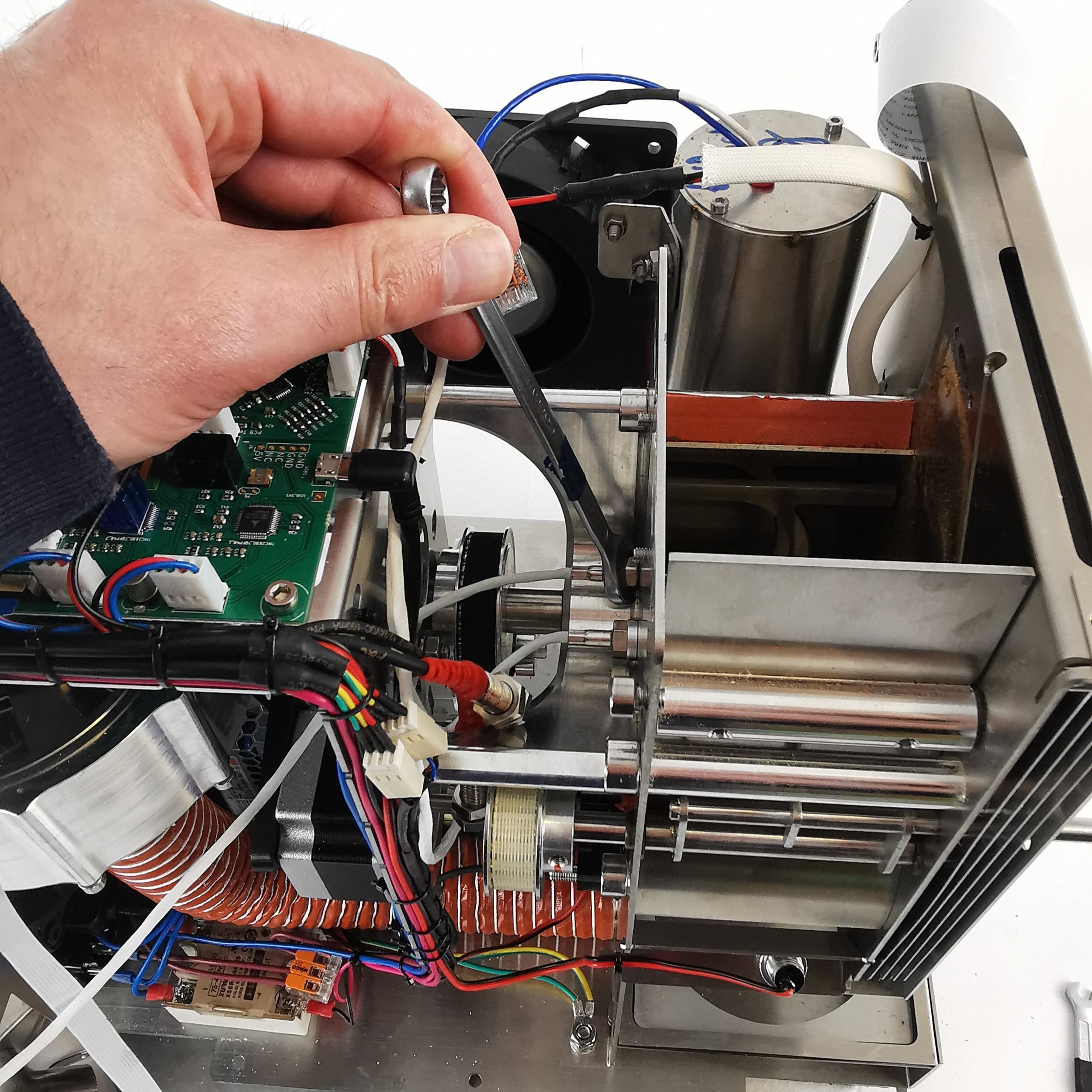
14. Remove the ET sensor.
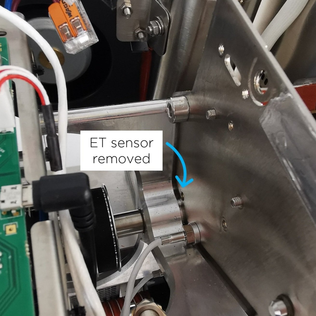
15. Take the new ET sensor and screw the M6 hexagonal nut onto the thread. The sensor should have a blacked-out area to indicate the length at which the sensor should be positioned in the drum.

16. Screw the ET sensor into the back plate. NOTE: Please ensure no resistance when rotating so as not to damage the thread in the back plate.

17. Before fastening, the orientation of the sensor is critical for it to work. From the front of the roaster, the orientation of the sensor must be as follows: The blue stripe should be on the right, and the white stripe in the middle should be completely vertical. If this criterion is met, fasten with the 10-millimeter wrench.
18. When fastening the sensor, ensure that nothing of the black area is visible inside the drum; if it is, you have screwed the sensor too far in.
19. If the criterion from steps 17 and 18 have been met, the nut can be tightened. Do not move forward until the orientation and length of the sensor have been set correctly.
20. Plug the ET sensor into the original spot on the PCB.

21. Tie two new cable ties to the motor bracket where you removed the cable ties earlier.


NOTE: Cable should not touch rotating pulley. This can damage/destroy the sensor over time.
22. Use cutters to trim excess ends on cable ties.

23. Continue to reassemble.

1. Push exhaust duct to original position

2. Tighten screws retaining bean-stopper

3. Install screw holding bean-stopper

4. Tighten FC grommets

5. Install exhaust pipe

6. Install charge handle

7. Screw the drop door sensors

8. Install FC card

9. Plug FC cable into PCB

10. First Crack card should NOT touch the back plate of the roaster.
24. Install side panels.
26. Plug the roaster in, turn it on and test the ET temperature sensor. Something is wrong if you see NaN on the touchscreen instead of a temperature where you normally read the ET temperature. Please contact the ROEST support team.
How to change: Drum window LED light
How to change the LED light of the drum window on your ROEST.

Where to buy drum window LED light?
If you are sure the LED light of the drum window is broken (you have talked to our Support Team) visit our e-shop to purchase a new one!
Before you start
⚠️DISCLAIMER
Information in this document is believed to be accurate and reliable. However, the manufacturer does not give any representations or warranties, expressed or implied, as to the accuracy or completeness of such information and shall have no liability for the consequences of the use of such information. The manufacturer is not liable or responsible for any problems arising from the attempted repair. The manufacturer reserves the right to make changes to information published in this document, including without limitation specifications and product descriptions, at any time and without notice. The manufacturer's products are not designed, authorized, or warranted to be suitable for use in applications where failure or malfunction can reasonably be expected to result in personal injury, death, or severe property or environmental damage. The manufacturer accepts no liability for inclusion and/or use of its products in such equipment or applications and therefore such inclusion and/or use is for the customer’s own risk.
⚠️SAFETY INSTRUCTIONS
make sure the roaster is turned off
the power cord has to be unplugged
follow the steps as instructed below
Tools

10-millimeter spanner/wrench/socket

2-millimeter hexagonal key

Cutters

Bean sample tray or similar, to prop the roaster at an angle for easy of disassembling
Parts

Plate 3 with LED light attached

Cable ties
Instructions
Step-by-step guide:
2. Remove the front décor plate.
3. Orientate the roaster so that the front is facing you. Lift the front of the roaster and place an item underneath to tilt the roaster back (for this example we have used a few sample trays).

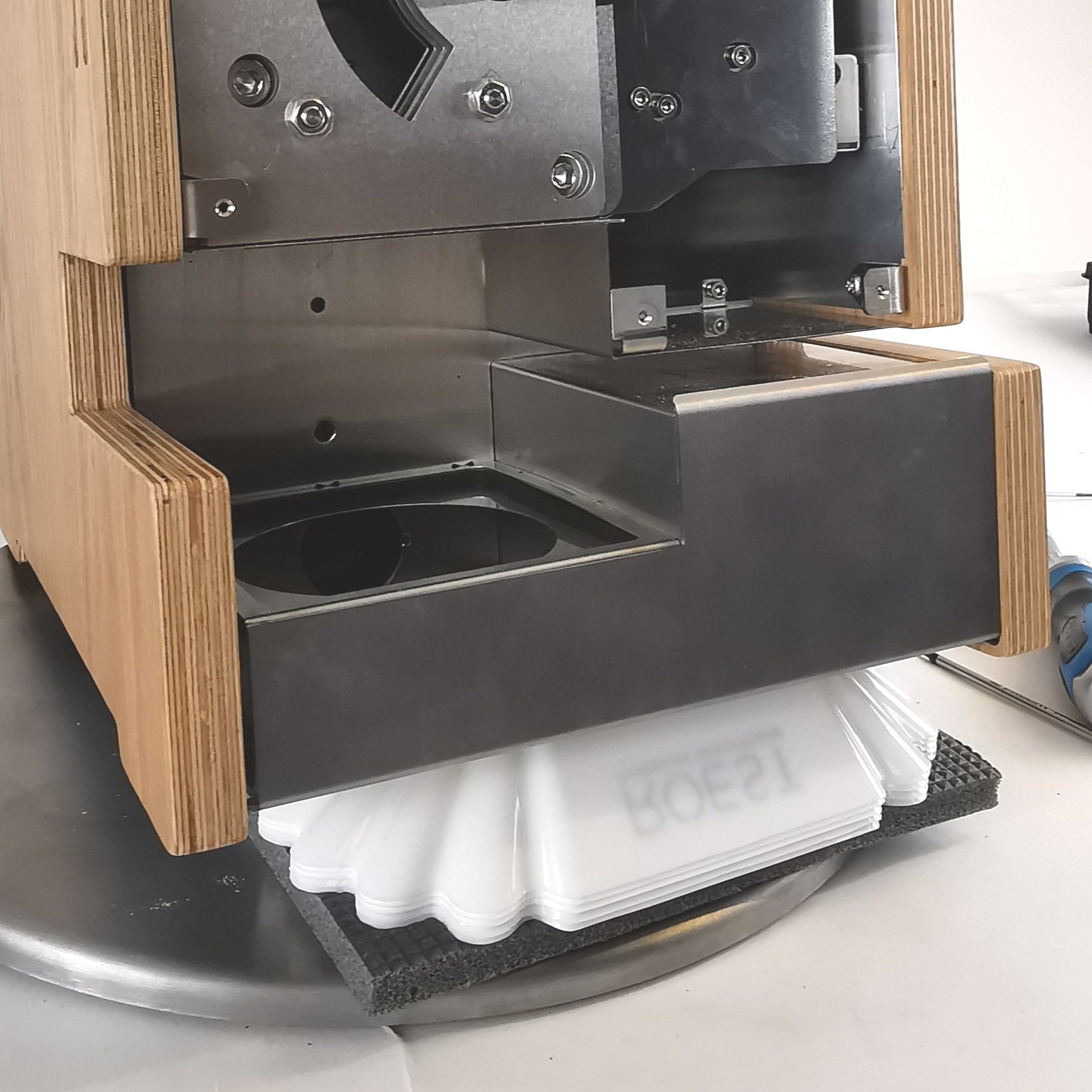
This is to give adequate access to the window LED and to enable the removal of aluminum spacers easier.
4. Remove the LED cable from the PCB and cut any cable ties securing it to the motor bracket.


5. Remove the protective sleeve and keep it for reinstallation. NOTE: if the protective sleeve is damaged, e.g., if a cable can be seen through the sleeve, discard it.

6. Pull the LED cable through the hole located in plate 1.


7. Remove the 6-millimeter nuts. Use the 10-millimeter wrench to loosen them and unscrew them by hand.


8. Remove plate 4 and the four aluminum spacers behind it.

1. Plate 4 removal

2. Take off the spacers
9. Remove plate 3 with the old LED light.

Plate 3 removal

This plate can be scrapped. Separate the metal part from the electronic part, and dispose of it responsibly.
NOTE: Check if the aluminum spacer is stuck to the backside of “Plate 3”; remove the spacer if it has adhered to the aluminum tape.
10. Install the new plate 3 with LED.

1. Ensure that the four aluminum spacers are on top of plate 2.

2. Install the new plate 3 and leave the cable loose.
11. Install the four aluminum spacers on top of Plate 3.

12. Install plate 4.
Install the four nuts and tighten them with the 10-millimeter wrench. NOTE: do not over-tighten the nuts, as this could damage the threads and the subsequent plates.

13. Feed the LED cable through the hole in plate 1 (this plate is the widest of the four plates).

14. Feed the protective sleeve over the end of the LED cable where it should touch the backside of plate 1.


15. Cable tie the protective sleeve and LED cable to plate 1.

Cable tie the sleeve at the top of plate one.
16. Plug the LED cable back into the original location on the PCB. NOTE: the PCB location reads “LED2”.

17. Tie loose cables to the motor bracket.

18. Install front décor plate.
20. Plug the roaster in, turn it on and test the drum window LED light. If it doesn’t work, contact the ROEST support team.
Video instructions
How to remove and install front décor plate

Before you start
⚠️DISCLAIMER
Information in this document is believed to be accurate and reliable. However, the manufacturer does not give any representations or warranties, expressed or implied, as to the accuracy or completeness of such information and shall have no liability for the consequences of the use of such information. The manufacturer is not liable or responsible for any problems arising from the attempted repair. The manufacturer reserves the right to make changes to information published in this document, including without limitation specifications and product descriptions, at any time and without notice. The manufacturer's products are not designed, authorized, or warranted to be suitable for use in applications where failure or malfunction can reasonably be expected to result in personal injury, death, or severe property or environmental damage. The manufacturer accepts no liability for inclusion and/or use of its products in such equipment or applications and therefore such inclusion and/or use is for the customer’s own risk.
⚠️SAFETY INSTRUCTIONS
make sure the roaster is turned off
the power cord has to be unplugged
follow the steps as instructed below
Tools

2 and 3-millimeter hexagonal tool
How to remove front décor plate
1a. Pull out the trier and the drop handle.
The black drop handle is attached by a set screw. Use the 3-millimeter hexagonal tool to remove it.


For the wooden drop handle, just pull it to take it off.
2. Disconnect the touchscreen cable from PCB. Push back the black retaining clip and detach the cable. Ensure the retaining clip is left in place at the connection point.


3. Remove the three front plate screws by using the 2-millimeter hexagonal tool.

4. Slowly remove the front décor plate from the roaster. Take off the front décor plate and place it on a protective surface. Leave the 40-pin cable connected to the screen.


How to install front décor plate
1. Feed the touchscreen cable through the original slots on the roaster and put the front décor plate in its position.

1. Cable through the frontal slot

2. Front décor plate installation

3. Cable through the top slot
2. Install the touchscreen cable into the PCB. Push the black retaining clip and insert the cable (you must twist it to show the blue band of the cable facing up).

You can use a flat head screwdriver to keep the clip “open” while inserting the cable.

Once in position, fasten it by pushing the clip back to its original position.
3. Install three M3 x 6 countersunk screws into the front décor plate by using the 2-millimeter hexagonal key.

4. Install the drop handle and the trier. For a wooden handle, push it through. For a black drop handle install the set screw using the 2-millimeter hexagonal tool.

How to change: Bean cooler LED light
How to replace a touch screen on your ROEST.

Where to buy LED light?
If you are sure your LED-light is broken (you have talked to our Support Team) visit our e-shop to purchase a new one!
Before you start
⚠️DISCLAIMER
Information in this document is believed to be accurate and reliable. However, the manufacturer does not give any representations or warranties, expressed or implied, as to the accuracy or completeness of such information and shall have no liability for the consequences of the use of such information. The manufacturer is not liable or responsible for any problems arising from the attempted repair. The manufacturer reserves the right to make changes to information published in this document, including without limitation specifications and product descriptions, at any time and without notice. The manufacturer's products are not designed, authorized, or warranted to be suitable for use in applications where failure or malfunction can reasonably be expected to result in personal injury, death, or severe property or environmental damage. The manufacturer accepts no liability for inclusion and/or use of its products in such equipment or applications and therefore such inclusion and/or use is for the customer’s own risk.
⚠️SAFETY INSTRUCTIONS
make sure the roaster is turned off
the power cord has to be unplugged
follow the steps as instructed below
Tools

Cutters
Parts

Bean cooler LED assembly

Cable ties to re-cable the LED light to the motor bracket.
Instructions
Step-by-step guide:
1. Remove the top plate. You can read how to do it here.
2. Remove the left side panel. Click here to see how to do it.
3. To know where to relocate and fasten the new LED light, you can take a photo of the cable location on the PCB (connector named LED1 on the PCB) and how cables are fastened to the motor bracket.

From top

From side
4. Disconnect bean cooler LED light cable from PCB.

5. Remove the old Bean Cooler LED Assembly. NOTE: if the LED is damaged, disassemble it from the bracket and dispose of it responsibly.


6. Cut cable ties to release LED cable by using the cutters.
CAUTION! take care not to cut through any cables. NOTE: Only cut the number of cable ties required to release that cable.


7. Slide the new bean cooler LED into position. NOTE: if the component does not locate by hand, gently tap the component into place until seated.


8. Plug the cable back into the PCB slot (connector named LED1).

9. Start tying the LED cable into position. Tie the LED cable into the remaining cables along the motor bracket.

Ensure that the cable has been fastened in position with a loop. This is in case the PCB needs to be changed.

IMPORTANT: Ensure that proximity extension cables are not cable tied.
10. Trim the excess from cable ties by using the cutters.
11. Before putting the left side panel and top plate back on the roaster, ensure that there is no excess cable from Bean Cooler LED Assembly that can be squeezed and damaged. IMPORTANT: If there is excess cable when the left side panel is fastened in place, this can cause the cable to become damaged and cause electrical faults in the roaster.

LED cable should look like this (no excess)
12. Install the left side panel.
13. Install the top plate.
14. Plug the roaster in, turn it on and test the LED light. If it doesn’t work, contact the ROEST support team.
How to change: PCB encoder
This is the guide on how to change the PCB encoder on your ROEST.

Where to buy PCB encoder?
If you are sure your encoder is broken (you have talked to our Support Team) visit our e-shop to purchase a new one!
Before you start
⚠️DISCLAIMER
Information in this document is believed to be accurate and reliable. However, the manufacturer does not give any representations or warranties, expressed or implied, as to the accuracy or completeness of such information and shall have no liability for the consequences of the use of such information. The manufacturer is not liable or responsible for any problems arising from the attempted repair. The manufacturer reserves the right to make changes to information published in this document, including without limitation specifications and product descriptions, at any time and without notice. The manufacturer's products are not designed, authorized, or warranted to be suitable for use in applications where failure or malfunction can reasonably be expected to result in personal injury, death, or severe property or environmental damage. The manufacturer accepts no liability for inclusion and/or use of its products in such equipment or applications and therefore such inclusion and/or use is for the customer’s own risk.
⚠️SAFETY INSTRUCTIONS
make sure the roaster is turned off
the power cord has to be unplugged
follow the steps as instructed below
Tools

2-millimeter hexagonal key

10-millimeter spanner/wrench/socket
Parts

Encoder PCB
Instructions
Step-by-step guide:
1. Remove the top plate and cable. You can read how to do it here.
2. Place the top plate on a protective surface and loosen the “grub screw” on the encoder knob. Use the 2-millimeter hexagonal key.
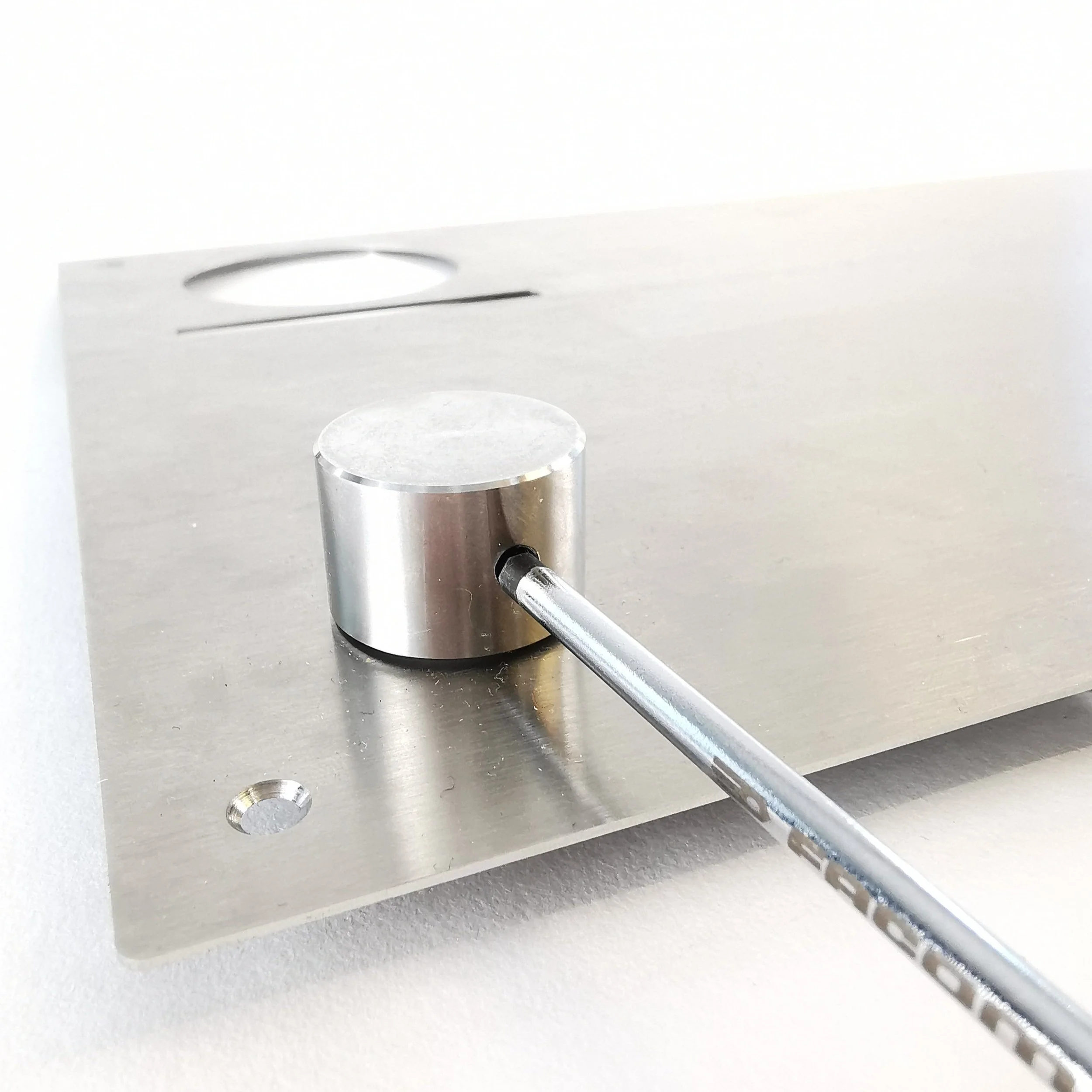
3. Remove the encoder knob and nylon washer.


4. Use the 10-millimeter spanner/wrench/socket to loosen the retaining nut and remove it. Take off the old encoder PCB and screw the nut back onto the threaded portion.
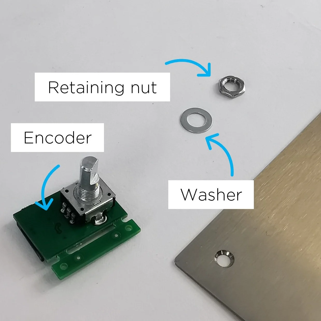
5. Take the new encoder PCB, and remove the retaining nut and the washer.
6. Locate the D-Shaped encoder PCB portion through the top plate hole.


7. Locate the washer and retaining nut on the threaded part (on the other side of the top plate).

First, fasten it by hand, and tighten it using the 10-millimeter wrench.

The orientation of the encoder must be as original. If not, the top plate will not fit. See D-shaped portion orientation.
8. Place the encoder knob (including the nylon washer) on top of the D-Shaped portion.

Align the grub screw hole with the flat portion of D Shape.

9. Tighten it by using the 2-millimeter hexagonal key.

10. Install the top plate and the encoder cable.
11. Plug the roaster in, turn it on and test the encoder. If it doesn’t work, contact the ROEST support team.
-
Adjustable roasting parameters
Service menu - includes recommended settings for motor gear ratio, cooling fan, heater fan, and PID settings.
-